Understanding hydraulic hose flow and velocity is crucial for anyone working with hydraulic systems. These two interconnected factors directly impact system efficiency, longevity, and even safety. Proper management ensures optimal performance and prevents common issues.
This blog post will delve into the fundamental principles governing flow and velocity within hydraulic hoses. We’ll explore how they influence pressure, heat generation, and component lifespan, providing insights to help you design and maintain more effective hydraulic systems.
What is Flow for Hydraulic Hose?
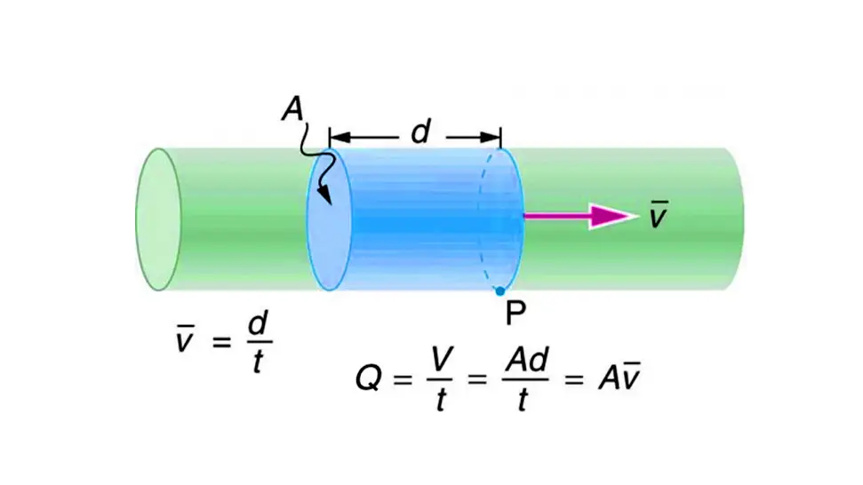
In the industry of a hydraulic hose, “flow” refers to the movement of hydraulic fluid through the hose. More specifically, it’s the volume of fluid that passes through a given cross-sectional area of the hose within a specific period of time.
This is commonly measured in units like gallons per minute (GPM) or liters per minute (LPM). Flow rate is a critical factor because it directly dictates how quickly hydraulic actuators (like cylinders or motors) will operate and how much power the system can deliver.
How to Calculate Hydraulic Hose Flow Rate?

Calculating hydraulic hose flow rate is essential for proper system design and performance. There are a few ways to approach this, depending on what information you already have.
The most common way to relate flow rate (Q) to velocity (V) and the hose’s internal diameter (D) is using the continuity equation:
Q = A × V
Where:
- Q is the flow rate (e.g., in cubic inches per minute, or converted to GPM/LPM)
- A is the cross-sectional area of the hose (in square inches or square centimeters)
- V is the fluid velocity (e.g., in inches per minute or feet per second)
To use this formula:
- Calculate the hose’s cross-sectional area (A):
- If you have the inner diameter (D): A=π×(D/2)2 or A=π×D2/4
- Make sure your diameter units are consistent with your desired flow rate units.
- Determine the fluid velocity (V):
- This is often a design consideration. Hydraulic systems have recommended velocity ranges for different lines (suction, pressure, return) to optimize performance and minimize issues like excessive pressure drop, heat generation, and noise. Typical recommendations are:
- Suction lines: 2-4 ft/sec (0.6-1.2 m/s)
- Pressure lines (up to 3000 psi / 207 bar): 15-20 ft/sec (4.6-6.1 m/s)
- Pressure lines (over 3000 psi / 207 bar): 25 ft/sec (7.6 m/s)
- Return lines: 10-15 ft/sec (3.0-4.6 m/s)
- This is often a design consideration. Hydraulic systems have recommended velocity ranges for different lines (suction, pressure, return) to optimize performance and minimize issues like excessive pressure drop, heat generation, and noise. Typical recommendations are:
- Perform the calculation and convert units as needed:
- If your diameter is in inches and velocity in feet per second, you’ll get cubic feet per second. You’ll then need to convert this to more common hydraulic units like GPM (gallons per minute) or LPM (liters per minute).
- Common conversion factors:
- 1 US gallon = 231 cubic inches
- 1 foot = 12 inches
- 1 minute = 60 seconds
Example (using common imperial units):
Let’s say you have a hose with an inner diameter (D) of 0.5 inches and a desired fluid velocity (V) of 15 feet per second.
- Calculate Area (A): A=π×(0.5 in)2/4=3.14159×0.25 in2/4=0.1963 in2
- Convert Velocity to inches per minute: V=15 ft/sec×12 in/ft×60 sec/min=10,800 in/min
- Calculate Flow Rate (Q) in cubic inches per minute: Q=A×V=0.1963 in2×10,800 in/min=2120.04 in3/min
- Convert to Gallons Per Minute (GPM): QGPM=2120.04 in3/min/231 in3/gallon≈9.18 GPM
Alternative Methods and Considerations:
- Nomographs: Many hydraulic component manufacturers provide nomographs (charts) that visually connect flow rate, velocity, and hose inner diameter. These are quick and easy to use for estimations.
- Online Calculators: Numerous online calculators are available (from manufacturers like Gates, Parker, Kingdaflex, etc.) that simplify these calculations and often account for additional factors like fluid viscosity, pressure drop, and hose length.
- System Requirements: Often, you’ll start with the flow rate required by your hydraulic actuators (e.g., a cylinder needs a certain GPM to extend at a specific speed). Then, you’ll use this flow rate and the desired velocity to select the appropriate hose size.
- Pressure Drop: While the primary formula relates flow, area, and velocity, actual flow rate in a real system is also affected by factors like fluid viscosity, hose length, bends, and system pressure. Excessive pressure drop can reduce effective flow.
- Turbulence vs. Laminar Flow: Maintaining an appropriate velocity helps ensure laminar flow, which is more efficient. High velocities can lead to turbulent flow, increasing heat generation and energy loss. The Reynolds Number is used to determine if flow is laminar or turbulent.
For precise calculations and critical applications, it’s always recommended to consult hydraulic engineering professionals or refer to specific manufacturer guidelines.
What is Velocity for Hydraulic Hose?
In the industry of a hydraulic hose, “velocity” refers to the speed at which the hydraulic fluid is moving through the hose. It is typically measured in units like feet per second (ft/s) or meters per second (m/s).
Fluid velocity is a critical parameter in hydraulic system design because it directly impacts pressure drop, heat generation due to friction, and the potential for cavitation (formation of vapor bubbles in the fluid due to low pressure). Maintaining fluid velocity within recommended ranges for different parts of a hydraulic circuit (e.g., suction, pressure, and return lines) is essential for efficient, safe, and long-lasting system operation.
How to Calculate Hydraulic Hose Velocity?
Calculating hydraulic hose velocity is fundamentally linked to the flow rate and the internal dimensions of the hose. The core principle is based on the idea that the volume of fluid flowing per unit of time (flow rate) is equal to the cross-sectional area of the hose multiplied by the speed at which the fluid is moving (velocity).
The most common formula for calculating hydraulic hose velocity (V) is derived from the continuity equation (Q = A × V), rearranged to solve for V:
V = Q / A
Where:
- V = Fluid velocity (e.g., in feet per second (ft/s) or meters per second (m/s))
- Q = Flow rate (e.g., in cubic feet per second, cubic meters per second, or more commonly, converted from gallons per minute (GPM) or liters per minute (LPM))
- A = Cross-sectional area of the hose (e.g., in square feet or square meters)
To use this formula effectively, you’ll need to follow these steps and ensure consistent units:
- Determine the Flow Rate (Q):
- This is typically known from your pump’s output or the requirements of your hydraulic actuators. Ensure your flow rate is in a volumetric unit that can be easily converted to match your area and velocity units (e.g., GPM to cubic inches per minute, then to cubic feet per second).
- Calculate the Hose’s Internal Cross-Sectional Area (A):
- You’ll need the inside diameter (ID) of the hydraulic hose.
- The formula for the area of a circle is: A=π×(ID/2)2 or A=π×ID2/4.
- Make sure your ID units are consistent with your desired velocity units. For example, if you want velocity in feet per second, you might convert your hose ID to feet first.
Common Formulas for Direct Calculation (with Unit Conversion Factors built-in):
Often, simplified formulas are used in the hydraulic industry that incorporate common unit conversions:
For Imperial Units:
V=(0.3208×Q)/D2
Where:
- V = Velocity in feet per second (ft/s)
- Q = Flow rate in US gallons per minute (GPM)
- D = Inside diameter of the hose in inches (in.)
For Metric Units:
V=(21.22×Q)/D2
Where:
- V = Velocity in meters per second (m/s)
- Q = Flow rate in liters per minute (LPM)
- D = Inside diameter of the hose in millimeters (mm)
Example (using Imperial Units formula):
Let’s say you have a flow rate (Q) of 10 GPM and a hose with an inside diameter (D) of 0.75 inches.
V=(0.3208×10)/(0.75)2 V=3.208/0.5625 V≈5.70 ft/s
Why is calculating velocity important?
- Optimal Performance: There are recommended velocity ranges for different types of hydraulic lines (suction, pressure, return) to optimize system performance.
- Suction lines: Typically 2-4 ft/s (0.6-1.2 m/s) to prevent cavitation (voids in the fluid) which can damage the pump.
- Pressure lines (low to medium pressure): 10-20 ft/s (3-6 m/s). Higher pressures might allow slightly higher velocities.
- Return lines: 10-15 ft/s (3-4.5 m/s).
- Pressure Drop: Higher velocities lead to increased friction and thus greater pressure drop along the hose, which can reduce the effective power delivered to actuators.
- Heat Generation: Friction also generates heat. Excessive velocity can lead to overheating of the hydraulic fluid, degrading its properties and shortening component life.
- Noise and Vibration: High velocities can contribute to increased noise and vibration in the system.
- Component Wear: Turbulent flow (often caused by excessive velocity) can lead to accelerated wear of internal hose linings and fittings.
By calculating and maintaining appropriate fluid velocities, you ensure your hydraulic system operates efficiently, reliably, and with a longer lifespan. Many hydraulic component manufacturers and online resources also provide convenient nomographs and calculators to assist with these calculations.
Conclusion
Mastering the concepts of hydraulic hose flow and velocity is essential for maximizing the efficiency and lifespan of your hydraulic systems. By carefully considering these factors during design and maintenance, you can prevent costly breakdowns, reduce energy consumption, and ensure safer operations.
Proper hydraulic hose selection, based on accurate flow and velocity calculations, is key to achieving these benefits. Overlooking these critical aspects can lead to pressure drops, excessive heat, and premature hose failure, ultimately impacting your system’s overall performance and reliability.
For wholesale hydraulic hoses that meet the demands of your applications, look no further than Kingdaflex. We offer a wide range of hoses designed to optimize your system’s flow and velocity, ensuring peak performance and durability.


