Accurately measuring hydraulic fittings is a fundamental skill for anyone working with fluid power systems. The correct identification and sizing of these components are crucial for ensuring leak-free connections, optimal system performance, and, most importantly, safety. Mismeasurement can lead to costly downtime, fluid leaks, and potential equipment damage.
This guide will demystify the process of measuring hydraulic fittings, breaking down the key steps and essential tools required. Whether you’re replacing a worn part or designing a new hydraulic circuit, understanding how to precisely measure thread size, pitch, and sealing surfaces will empower you to make informed decisions and maintain efficient operations.
What to Measure for Hydraulic Fittings
When working with hydraulic systems, accurately identifying and measuring fittings is paramount for ensuring leak-free connections and system integrity. This process isn’t just about obtaining a single dimension; rather, it involves a series of precise measurements and identifications to determine the fitting’s type, size, and sealing method. Using the correct tools, such as calipers, thread pitch gauges, and seat angle gauges, is essential for obtaining reliable readings.
Misidentifying or incorrectly measuring a hydraulic fitting can lead to severe consequences, including fluid leaks, pressure loss, component damage, and potential safety hazards. Therefore, a systematic approach is necessary, starting with visual identification of the fitting’s general characteristics and then moving on to specific dimensional checks. This thoroughness ensures that any replacement or new fitting will perfectly match the existing system’s requirements.
Here’s what you need to measure for hydraulic fittings:
Hydraulic Fitting Type: Identify the overall design and sealing mechanism (e.g., JIC flare, ORFS O-ring face seal, NPT tapered pipe thread, BSPP parallel thread, etc.). This is often the first step, as different types require different measurement approaches for their sealing surfaces.
Thread Diameter:
- For male threads, measure the outside diameter (OD) of the threads.
- For female threads, measure the inside diameter (ID) of the threads.
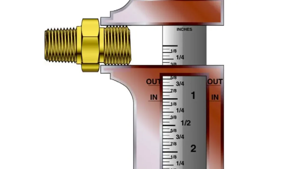
- Use a caliper for precision, measuring across the peaks of the threads.
Thread Pitch: Determine the number of threads per inch (TPI) for imperial threads or the distance between threads in millimeters for metric threads. A thread pitch gauge is the most accurate tool for this.
Sealing Surface Measurement: This is crucial and varies by fitting type:
- For JIC (37° Flare) Fittings: Measure the diameter of the 37-degree conical flare. For male fittings, measure the OD of the cone at its widest point. For female fittings, measure the ID of the cone at its narrowest point.
- For O-Ring Face Seal (ORFS) Fittings: Measure the OD of the male fitting’s flat face and the ID of the female fitting’s flat face. Also, note the presence and size of the O-ring groove.
- For Tapered Pipe Threads (NPT, BSPT): While diameter and pitch are key, the seal is made by the thread taper itself. Visual inspection for taper is important.
- For Parallel Threads (BSPP, ORB): The seal relies on an O-ring or a bonded washer, so identifying the presence and location of this sealing element is vital.
Overall Length and Shape (for specific applications): While not always directly part of the sealing mechanism, the overall length of the fitting, and whether it’s a straight, elbow, or tee, is necessary for proper routing and installation within the system.
How to Measure Hydraulic Fittings?

Accurately measuring hydraulic fittings is paramount for ensuring proper fit, preventing leaks, and maintaining the integrity of your hydraulic system. Incorrect measurements can lead to costly downtime and potential safety hazards.
This guide will walk you through the essential steps to correctly identify and measure various hydraulic fittings.
Tools Needed:
Accurately measuring hydraulic fittings requires more than just a keen eye; specialized tools are essential for obtaining the precise dimensions needed for proper identification and selection. Having the right instruments on hand ensures that measurements are reliable, preventing costly errors and ensuring a secure, leak-free hydraulic system.
Here are the essential tools needed:
- Caliper: An indispensable tool for measuring outside diameters (OD) of male threads, inside diameters (ID) of female threads, and various other component dimensions with high precision. Both digital and analog calipers are suitable.
- Thread Pitch Gauge: A set of metal blades with various thread profiles used to accurately determine the number of threads per inch (TPI) or the thread pitch (distance between threads) for both imperial and metric threads.
- Angle Gauge (or Protractor with Angle Finder): Useful for verifying the flare angle of fittings like JIC (37°) or SAE (45°), especially when visual identification is difficult or confirmation is needed.
- Cleaning Supplies: Rags or brushes to clean dirt, grease, or corrosion from the fitting threads and sealing surfaces before measurement, as debris can lead to inaccurate readings.
- Magnifying Glass (Optional but Recommended): Can be helpful for closely inspecting small threads or subtle features on the fitting to ensure accurate identification.
Step 1: Identify the Fitting Type
The first and most critical step is to correctly identify the type of hydraulic fitting you are working with. Different fitting types utilize distinct sealing methods and require specific measurement approaches. Common types include JIC (37-degree flare), O-Ring Face Seal (ORFS), NPT (tapered pipe thread), BSPP (British Standard Parallel Pipe), and flange fittings, among others.
Visual inspection is often the initial clue. For instance, JIC fittings have a distinct 37-degree conical seat, while ORFS fittings feature a flat face with an O-ring groove. NPT and BSPT fittings will have visible threads that are tapered, whereas BSPP threads are parallel and usually seal with an O-ring or bonded washer. Correctly identifying the type narrows down the subsequent measurement parameters significantly.
Step 2: Measure the Thread Diameter
Once the fitting type is identified, measuring the thread diameter is the next crucial step. For male fittings, use a caliper to measure the outside diameter (OD) of the threads at their widest point (the crest). For female fittings, measure the inside diameter (ID) of the threads. It’s important to measure across the actual threads, not just the base or the overall body.
This measurement provides the nominal size of the fitting, which can then be cross-referenced with standard sizing charts for various fitting types. Remember that thread measurements are often nominal, meaning the actual measurement may not be an exact whole number, but it will correspond to a recognized standard size (e.g., a measurement near 0.65 inches might indicate a 1/2-inch fitting).
Step 3: Determine the Thread Pitch
Following the diameter measurement, accurately determining the thread pitch is essential, especially for threaded fittings. Thread pitch refers to the number of threads per inch (TPI) for imperial threads or the distance between threads (in millimeters) for metric threads. This measurement differentiates between threads of the same diameter but different pitches, preventing cross-threading and ensuring a proper seal.
The most precise way to determine thread pitch is by using a thread pitch gauge. This tool has a series of blades, each with a specific thread profile. You simply match the blades to the threads of your fitting until you find one that fits perfectly without any gaps or wobbling. For a quick approximation, you can also count the number of threads within a known length (e.g., 0.5 or 1 inch) on the fitting.
Step 4: Measure the Sealing Surface
The final and arguably most critical measurement involves the sealing surface, which varies significantly depending on the fitting type. This measurement directly influences the fitting’s ability to create a leak-proof connection.
For JIC fittings, measure the diameter of the 37-degree conical flare. For male JIC fittings, measure the outside diameter of the cone at its largest point. For female JIC fittings, measure the inside diameter of the cone at its smallest point. For ORFS fittings, measure the outside diameter of the flat face on the male fitting and the inside diameter of the flat face on the female fitting, also noting the O-ring groove’s dimensions. For parallel thread fittings that seal with a washer or O-ring (like BSPP or ORB), ensure the seating surface for that seal is intact and measure its diameter if relevant to the sealing method. For tapered pipe threads (NPT, BSPT), the taper itself is the sealing mechanism, and while no specific “sealing surface diameter” is measured, verifying the taper angle is key.
How to Measure Hydraulic Fitting Thread Size?
Accurately measuring the thread size of a hydraulic fitting is a fundamental skill for anyone working with fluid power systems. Precise measurements are crucial for ensuring a perfect fit, preventing leaks, and maintaining the operational integrity of your machinery. This process involves more than just a quick glance; it requires careful attention to detail and the use of specific measuring tools.
Understanding the various thread types and how they are measured is key to avoiding costly mistakes. Whether you’re dealing with tapered, parallel, or flared connections, each thread type has its own characteristics that influence its size and sealing mechanism.
Following a systematic approach ensures that you accurately identify and size the fitting, leading to reliable connections.
Step 1: Identify the Thread Type
Before any measurements are taken, it is essential to correctly identify the type of thread you are examining. Hydraulic systems commonly use several thread standards, including NPT (National Pipe Tapered), BSPT (British Standard Pipe Tapered), BSPP (British Standard Parallel Pipe), SAE (Society of Automotive Engineers) straight thread O-ring boss, and various flare fittings like JIC (37° flare). Each of these has distinct characteristics in terms of taper, parallelism, and sealing method.
Visually inspect the threads to determine if they are tapered (narrowing towards the end) or parallel. Also, observe if there’s a sealing feature beyond the threads themselves, such as a conical flare or a flat face for an O-ring. Correctly identifying the thread type from the outset will guide your subsequent measurement steps and help you select the appropriate measuring tools.
Step 2: Measure the Thread Diameter
Once the thread type is identified, the next critical step is to measure the thread diameter. For male fittings, use a caliper to measure the outside diameter (OD) of the threads. Place the caliper jaws across the widest part of the threads (the crests). For female fittings, measure the inside diameter (ID) of the threads. Ensure the caliper is positioned firmly and squarely for an accurate reading.
It’s important to remember that thread sizes are typically expressed as nominal values (e.g., 1/2 inch, 3/4 inch), and the actual measured diameter may not be an exact whole number. Instead, the measurement will correspond closely to a standard nominal size. Take multiple measurements if necessary to confirm your reading and account for any potential wear or imperfections on the threads.
Step 3: Determine the Thread Pitch
After measuring the diameter, the thread pitch is the next crucial dimension to ascertain. Thread pitch refers to the distance between individual threads, often expressed as threads per inch (TPI) for imperial threads or as a millimeter measurement between crests for metric threads. This measurement is vital for differentiating between threads of the same nominal diameter but different pitches, preventing cross-threading and ensuring a secure connection.
The most accurate tool for determining thread pitch is a thread pitch gauge. This tool consists of several blades, each precisely engineered with a different thread profile. Simply place the blades onto the fitting’s threads until you find the one that fits perfectly, with no gaps or wobbling. The number indicated on the matching blade will be your thread pitch. Without a gauge, a less precise method involves carefully counting the number of thread crests over a measured distance (e.g., 1/2 inch or 1 inch) and then extrapolating to determine the TPI.
Step 4: Account for Sealing Surface (If Applicable)
While thread diameter and pitch define the thread itself, for many hydraulic fittings, the sealing mechanism is separate from, or in addition to, the threads. Therefore, measuring or identifying the sealing surface is a crucial final step for complete sizing. For flare fittings like JIC, the seal is made by a 37-degree cone, so you would measure the diameter of this cone (the outside diameter of the male flare, or the inside diameter of the female flare).
For O-Ring Face Seal (ORFS) fittings, the seal relies on an O-ring compressed against a flat face; here, you would measure the outside diameter of the flat face on the male fitting and the inside diameter of the flat face on the female fitting, in addition to noting the O-ring size. For parallel threads (like BSPP or SAE O-ring Boss), the threads secure the fitting, but a separate sealing element (like an O-ring or bonded washer) creates the seal. In these cases, verifying the presence and location of this sealing surface is just as important as the thread dimensions.
How to Determine Hydraulic Fitting Size
Accurately determining hydraulic fitting size is crucial for ensuring a safe, leak-free, and efficient hydraulic system. Mismatched fittings can lead to serious operational issues, including pressure loss, component damage, and even catastrophic failure. This process often involves precise measurements and consulting relevant industry standards.
1. Identify the Fitting Type
Before measuring, it’s important to identify the type of hydraulic fitting. Common types include JIC (Joint Industry Council), NPT (National Pipe Taper), BSPP (British Standard Pipe Parallel), ORFS (O-Ring Face Seal), and various Metric (DIN) fittings. Each type has distinct thread profiles, sealing methods, and measurement considerations. Knowing the fitting type will guide you in using the correct measurement tools and reference charts.
2. Measure Thread Diameter
Using precision measuring tools like calipers, measure the outside diameter (OD) of male threads and the inside diameter (ID) of female threads. For male threads, measure across the widest part of the threads. For female threads, insert the caliper jaws into the fitting and expand them until they touch the inside walls. It’s crucial to measure accurately, as even slight discrepancies can mean a mismatch.
3. Determine Thread Pitch
Thread pitch is the distance between individual threads. For imperial threads, this is often expressed as threads per inch (TPI). For metric threads, it’s the distance in millimeters between two adjacent thread crests. A thread pitch gauge is the most effective tool for this step; simply place the gauge teeth onto the threads until you find a tight fit with no gaps. If a gauge isn’t available, you can use calipers to estimate the distance over a known number of threads and then calculate the pitch.
4. Measure Seat Angle (if applicable)
Many hydraulic fittings, like JIC or SAE 45° flare fittings, rely on a specific seat angle for sealing. Use a protractor or a specialized angle-measuring tool designed for hydraulic fittings to determine this angle. Common angles are 37° for JIC, 45° for SAE flare, or various cone angles for metric fittings. An incorrect seat angle will prevent a proper seal, leading to leaks.
5. Consult Our Hydraulic Fitting Chart
Once you have taken all necessary measurements (thread OD/ID, pitch, and seat angle), compare these measurements against comprehensive hydraulic fitting size charts. We have all of. these hydraulic fitting size charts, readily available from our hydraulic fitting manufacturer and industry standard organizations (e.g., SAE, ISO). Here we list the standard dimensions for various hydraulic fitting types and sizes, allowing you to accurately identify the specific fitting you need.
How Do I Know What Size Hydraulic Fitting I Have?
Identifying the correct size of a hydraulic fitting is crucial for ensuring a leak-free and safe connection in any fluid power system. It’s a precise process that goes beyond simply looking at the fitting, as many types can appear similar but have critical differences in their dimensions and sealing methods. Misidentification can lead to costly downtime, fluid leaks, and potential safety hazards.
To accurately determine the size of a hydraulic fitting, you need to employ a systematic approach using specific measuring tools and referencing industry standard charts. The process involves identifying the fitting type, carefully measuring its thread dimensions, and then verifying the sealing surface, all of which contribute to the overall “size” of the fitting.
Here’s how to know what size hydraulic fitting you have:
Identify the Fitting Type:
- Visual Inspection: Look at the shape of the fitting’s end and how it’s designed to seal. Does it have a 37-degree cone (JIC)? A flat face with an O-ring (ORFS)? Tapered threads (NPT/BSPT)? Parallel threads with a seat for a washer or O-ring (BSPP/ORB)?
- Common Types: Familiarize yourself with the visual characteristics of common hydraulic fitting types, such as JIC (37° flare), ORFS (O-ring face seal), NPT (National Pipe Tapered), BSPP (British Standard Parallel Pipe), and SAE O-ring Boss (ORB).
Measure the Thread Diameter:
- Male Threads: Use a caliper to measure the outside diameter (OD) of the threads at their widest point (the crests).
- Female Threads: Use a caliper to measure the inside diameter (ID) of the threads.
- Consistency: Take several measurements to ensure accuracy and account for any wear or irregularities. Note that these measurements will typically be nominal values (e.g., 0.745 inches for a 3/4-inch thread).
Determine the Thread Pitch:
- Thread Pitch Gauge: This is the most accurate tool. Place the blades of the gauge onto the threads until you find one that fits perfectly with no light showing through. The gauge will indicate the threads per inch (TPI) for imperial threads or the distance between threads for metric threads.
- Counting Threads (Less Precise): For imperial threads, you can sometimes approximate by counting the number of threads within a 1-inch or 1/2-inch section of the fitting.
Measure the Sealing Surface:
- JIC (37° Flare): Measure the diameter of the 37-degree cone. For male fittings, measure the OD of the cone; for female fittings, measure the ID of the cone.
- ORFS (O-Ring Face Seal): Measure the OD of the flat face on the male fitting and the ID of the flat face on the female fitting. Also, note the size of the O-ring and its groove.
Other Types: For fittings that seal differently (e.g., NPT’s tapered threads), this step involves visual confirmation of the sealing method and ensuring no damage to that area.
Cross-Reference with Charts:
Once you have all the measurements (fitting type, thread diameter, thread pitch, and sealing surface dimension), compare these values to an industry-standard hydraulic fitting size chart. These charts are readily available online or from fitting manufacturers and will help you definitively determine the nominal size and type of your fitting.
Many charts also include “dash sizes” (e.g., -4, -6, -8) which correspond to common hose and fitting sizes, often based on the tube’s outer diameter in 1/16th inch increments.
Conclusion
Accurately measuring hydraulic fittings is crucial for the integrity and efficiency of any hydraulic system. As discussed, correctly identifying the fitting type, measuring thread diameter, determining thread pitch, and verifying the flare or sealing surface are all vital steps. Precision in these measurements directly translates to leak-free and durable connections, preventing costly operational failures.
Understanding the nuances of each measurement ensures that replacement or new fittings perfectly match existing components. This attention to detail not only optimizes system performance but also significantly enhances safety by mitigating the risks associated with improper fitting selection and installation. It’s an indispensable skill for anyone working with hydraulic machinery.
For reliable hydraulic system performance, sourcing high-quality components is paramount. You can get wholesale hydraulic fittings from Kingdaflex to ensure access to a comprehensive range of fittings that meet stringent industry standards, providing the precision and durability your applications demand.


