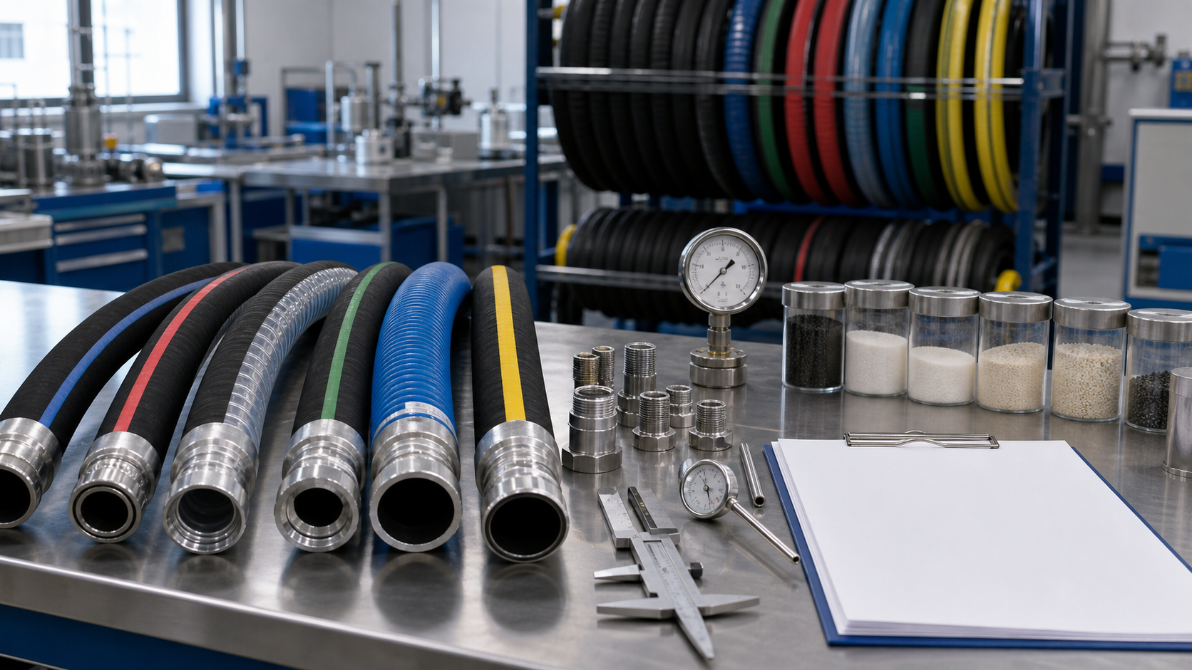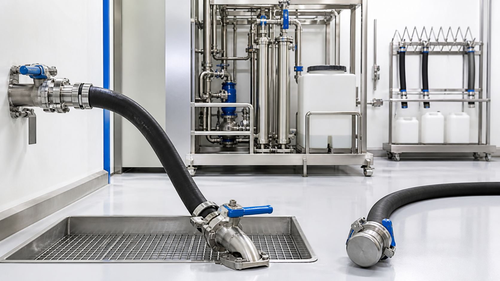
When a flammable liquid moves through a hose, electrostatic charge may be generated by flow, filtration, splashing, or mixing. If accumulated charge discharges as a spark in a flammable atmosphere, fire or explosion can result.
Selecting a conductive hose is only one part of controlling this hazard. A safe system may also require bonding between conductive components, grounding to earth, suitable fittings, verified electrical continuity, controlled flow, appropriate filling practices, and a site-specific hazardous-area assessment.
This guide explains the practical role of bonding and grounding fuel transfer hose assemblies. It does not replace applicable regulations, codes, equipment instructions, or review by a qualified safety professional.
Bonding, Grounding, and Conductive Hose Are Different
| Term | Basic purpose |
|---|---|
| Bonding | Connects conductive objects so they remain at similar electrical potential |
| Grounding | Connects a conductive object or bonded system to an approved earth reference |
| Conductive hose | Provides a designed electrical path through or along the hose assembly |
| Static-dissipative hose | Allows charge to decay within a defined resistance range |
| Non-conductive hose | Intentionally limits electrical conduction for specific applications |
These terms should not be used interchangeably. A conductive hose lying on the ground is not grounded. Bonding two containers does not necessarily connect them to earth. A wire helix inside a hose does not guarantee end-to-end continuity unless it is correctly incorporated into the fittings.
Review the difference between conductive and non-conductive hose before selecting a construction. The required electrical behavior must be defined for the actual transfer process.
How Static Charge Develops During Transfer
Charge separation can occur as liquid contacts the tube, flows through filters, passes restrictions, or enters a vessel. Accumulation depends on fluid conductivity, velocity, turbulence, temperature, hose construction, and equipment geometry.
Splash filling and free-falling streams can increase charging and may create mist or vapor. Filters, strainers, pumps, valves, and partially filled lines can influence the hazard. Some low-conductivity liquids retain charge longer because it dissipates slowly.
A flammable event requires more than static generation: a flammable atmosphere, sufficient discharge energy, and a discharge path must coincide. The control strategy aims to prevent that combination.
Begin with a Process Hazard Assessment
Before specifying the hose, identify:
- liquid identity, composition, conductivity, and temperature;
- flash point and possible vapor concentration;
- normal and maximum flow rates;
- loading, unloading, recirculation, and cleaning steps;
- source and receiving containers;
- pumps, filters, valves, meters, and nozzles;
- classified or hazardous-area requirements;
- potential isolated conductive objects;
- environmental conditions and ignition sources;
- applicable local codes, industry practices, and site standards.
Do not assume all fuel applications use the same control. A fixed bulk loading rack, marine bunkering system, portable drum transfer, service-station dispenser, and machine fuel line present different conditions.
Select a Hose Designed for the Service
The tube must be compatible with the fuel or flammable liquid, including additives, bio-components, and cleaning agents. The hose must also meet pressure, vacuum, temperature, bend radius, abrasion, weathering, and permeation requirements.
A rubber fuel hose may suit many fuel-transfer applications, but the exact grade and electrical construction must be confirmed. Do not infer conductivity from black color; carbon black can be used in compounds with very different electrical properties.
For vessels and dockside equipment, a marine fuel hose may also need resistance to saltwater, weather, movement, and marine operating conditions. The complete assembly—including fittings and accessories—must meet the relevant project requirements.
Understand Hose Conductive Paths
A hose can achieve electrical performance through a conductive tube or cover compound, embedded conductive wires, metallic helix, braid, or a designed combination. Each construction has specific assembly instructions.
If a bonding wire or helix must contact the coupling, the termination method is critical. Cutting the wire short, folding it incorrectly, insulating it with sealant, or using an incompatible fitting can break continuity. Conversely, exposing wire where it can corrode may cause progressive loss of performance.
Use only a hose-and-coupling system approved for the application. Follow the manufacturer’s preparation, fitting, crimping or clamping, and continuity-test procedure.
Create a Complete Bonding Path
All conductive components that could develop a dangerous potential difference may need to be bonded. Depending on the system, this can include the source tank, receiving vessel, pump, filter housing, piping, hose couplings, nozzle, intermediate container, skid, or vehicle.
Bonding connections should attach to designated clean conductive points. Paint, rust, dirt, coatings, loose hardware, and corrosion can create resistance. Temporary clips need suitable contact force, cable protection, and inspection.
Make the bonding connection before starting transfer and keep it connected until transfer is complete, valves are closed, and the process is in a safe state. The exact sequence should be defined in the site procedure.
Connect the System to an Approved Ground
Grounding provides a controlled path from the conductive system to earth. The correct ground point and conductor must be determined by the facility’s electrical and process-safety design. Random structural metal, handrails, or nearby piping should not be assumed to be an acceptable ground.
Temporary transfer operations need particular care because equipment location changes and the integrity of the grounding point may be unknown. Use engineered connection points and verification methods specified by the site.
Grounding requirements can interact with cathodic protection, electrical equipment, marine installations, and other systems. Qualified personnel should evaluate those interfaces.
Specify Electrical Performance Clearly
“Anti-static” is too vague for a purchase specification. Define the required end-to-end resistance or conductivity classification, test method, test voltage where applicable, acceptance limit, environmental conditions, and test frequency.
Different industries and hose types may use different limits. Copying a resistance value from an unrelated product can be unsafe. Consult the equipment manufacturer, applicable standards, and supplier of the selected industrial hose solutions.
State whether the measurement applies to the hose wall, cover, embedded conductor, coupling-to-coupling path, or entire installed system.
Test Continuity of New Assemblies
Verify electrical performance after assembly because fitting installation affects the conductive path. The record should identify the assembly, date, instrument, method, result, acceptance limit, and inspector.
Before testing, ensure the hose is clean, depressurized, and in a safe area. Use calibrated equipment appropriate to the resistance range. Contact the specified points consistently and avoid interpreting unstable readings without investigation.
If a new assembly fails, quarantine it. Do not add an improvised external wire unless the approved design explicitly allows it. Diagnose hose construction, wire termination, fitting contact, corrosion, contamination, and measurement method.
Inspect and Retest in Service
Electrical continuity can change through flexing, abrasion, crushing, wire breakage, coupling movement, corrosion, repairs, and chemical attack. Establish inspection and retest intervals based on hazard, usage, environment, manufacturer guidance, and site rules.
Inspect:
- hose cuts, cracks, blisters, kinks, and exposed reinforcement;
- loose, damaged, or corroded couplings;
- bonding clips, cables, lugs, and attachment points;
- continuity across swivels or adapters;
- evidence of overheating or arcing;
- legibility of identification and test status.
Retest after repair, coupling replacement, severe mechanical event, or suspected electrical damage. Remove failed assemblies from service until formally dispositioned.
Control Other Static-Related Factors
Bonding and grounding do not eliminate every ignition risk. The process may also require:
- controlled flow velocity;
- bottom filling or submerged fill pipes;
- settling time after filtration or transfer;
- avoidance of splash and free fall;
- suitable pumps and electrical equipment;
- ventilation and vapor control;
- approved containers and fittings;
- prevention of air entrainment;
- control of insulating clothing or surfaces;
- operating limits for weather conditions.
The appropriate controls must come from the process hazard assessment. A continuity test cannot compensate for an unsafe transfer method.
Avoid Common Mistakes
Frequent errors include assuming a metal coupling guarantees continuity, identifying hose conductivity by appearance, clipping onto painted metal, disconnecting the bond too early, failing to include intermediate equipment, and testing only when the assembly is new.
Another mistake is using a conductive hose where electrical isolation is intentionally required. Some electrical, welding, utility, or specialized applications need non-conductive performance. The system requirement must be established before purchase.
Procurement Checklist
An RFQ for flammable-liquid hose assemblies should define:
- exact fluid and operating conditions;
- required hose standard and electrical classification;
- pressure, vacuum, temperature, and movement;
- fitting and seal specifications;
- conductor termination method;
- end-to-end resistance requirement and test method;
- 100 percent or sampled test frequency;
- marking and traceability;
- inspection, retest, and retirement guidance;
- required certificates and reports.
Ask the supplier to identify assumptions and limitations rather than simply confirming “conductive.”
Final Safety Principle
Safe flammable-liquid transfer depends on a continuous, verified system—not a single hose feature. Hose construction, fittings, bonding, grounding, process conditions, equipment, procedures, inspection, and training must work together.
Define the electrical requirement before ordering, verify the completed assembly, and maintain the conductive path throughout service. That approach turns static control from an assumption into documented protection.