Hydraulic systems are the backbone of countless industries, powering everything from construction equipment to manufacturing machinery.
A critical component of these systems is the hydraulic hose, responsible for transporting pressurized fluid to various components. The flow rate of this fluid is paramount, as it directly impacts the system’s performance and efficiency.
In this comprehensive guide, we will delve into the intricacies of hydraulic hose flow rate, exploring factors that influence it, methods to calculate it, and strategies to optimize it for maximum system performance.
What Is Hydraulic Hose Flow Rate?
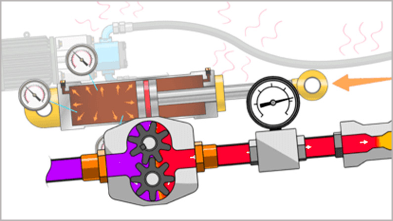
The hydraulic hose flow rate, or hydraulic flow, is defined as the volume of the substance that flows through the hydraulic hose inner tube cover a specific period of time. And the hydraulic hose flow rate can be mathematically represented by a capital letter Q.
And calculating the hydraulic hose flow rate is very important for hydraulic system engineering, to determine the right selection of the hydraulic hose used for the hydraulic system.
Does Hydraulic Hose Size Affect Flow Rate?
Yes, of course!
Choosing the right inner diameter for your hydraulic hose is crucial. If it’s too small, the fluid flow will be restricted, leading to increased heat, reduced efficiency, and excessive pressure drops. This can negatively impact your system’s overall performance. Conversely, if the inner diameter is too large, you’ll face higher costs and potential operational issues.
When fixing the hose with a pipe clamp or passing the hose through a steel plate, pay attention to the outer diameter of the hose. Using the relationship diagram of the hose flow, inner diameter, and flow rate, you can quickly select the appropriate hose inner diameter, as shown in the figure.
For example, the flow rate of the hydraulic system is 75 L/min, and the recommended flow rate of the pipeline is 6 m/s. Connect the two coordinate points to form a straight line, and the intersection of 15.9 mm with the pipeline inner diameter column is the required inner diameter of the hose.
How Do You Calculate the Flow Rate of A Hose?
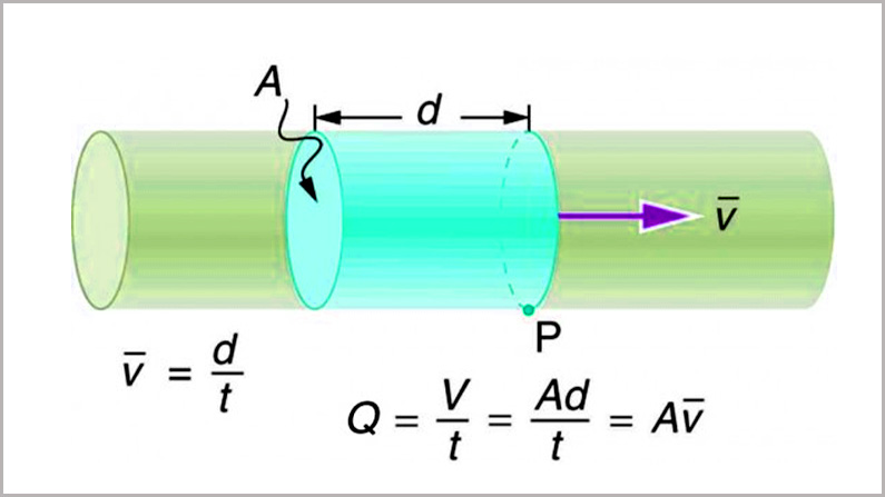
Here is the hydraulic hose flow rate formula, helping you calculate the result of hose flow rate. Flow rate Q is defined to be the volume of hydraulic fluid passing by through a hydraulic hose during a period of time.
Q=VtQ=Vt
For example, the heart of a resting adult pumps blood at a rate of 5.00 liters per minute (L/min).
Note that a liter (L) is 1/1000 of a cubic meter or 1000 cubic centimeters (10-3 m3 or 103 cm3). In this text, we shall use whatever metric units are most convenient for a given situation.
Hydraulic Hose Flow Rate Calculator
A hydraulic hose flow rate calculator is a digital tool designed to help engineers, technicians, and system designers determine the flow rate of fluid through a specific hydraulic hose.
By inputting key parameters such as hose diameter, pressure, and fluid viscosity, the calculator can provide accurate estimates of the fluid flow rate in gallons per minute (GPM) or liters per minute (LPM).
Hydraulic Hose Flow Rate Calculator
Why is a Flow Rate Calculator Important?
- Optimal System Design: Accurate flow rate calculations are essential for designing hydraulic systems that can deliver the required power and performance.
- Troubleshooting System Issues: By understanding the flow rate, technicians can identify potential problems, such as blockages or leaks, that may be affecting system performance.
- Selecting the Right Hose: The calculator helps in choosing the appropriate hose size and material to ensure efficient fluid flow and prevent excessive pressure drops.
- Energy Efficiency: Proper flow rate calculations can help optimize energy consumption by avoiding unnecessary pressure and flow.
Key Factors Affecting Hydraulic Hose Flow Rate:
- Hose Diameter: A larger diameter allows for higher flow rates.
- Fluid Pressure: Higher pressure can increase flow rate, but it’s essential to consider the hose’s pressure rating.
- Fluid Viscosity: Thicker fluids flow more slowly than thinner ones.
- Hose Length: Longer hoses can introduce more friction, reducing flow rate.
- Hose Material: The material of the hose can affect its flow resistance.
By utilizing a hydraulic hose flow rate calculator, you can make informed decisions to optimize your hydraulic system’s performance, efficiency, and reliability.
Would you like to learn more about specific factors affecting hydraulic hose flow rate or how to use a flow rate calculator?
Hydraulic Hose Flow Chart
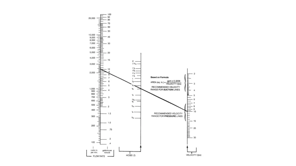
A hydraulic hose flow chart is a visual representation of the fluid flow path within a hydraulic system, specifically focusing on the hoses used to transport the fluid. It’s a valuable tool for understanding system design, troubleshooting issues, and selecting the appropriate hose for a given application.
Basic Elements of a Hydraulic Hose Flow Chart:
- Hydraulic Pump: The source of pressurized fluid.
- Hydraulic Hoses: Flexible tubes that carry the fluid to various components.
- Hydraulic Valves: Control the direction and flow rate of the fluid.
- Hydraulic Actuators: Convert fluid pressure into mechanical force or motion (e.g., cylinders, motors).
- Hydraulic Reservoir: Stores excess fluid and acts as a heat sink.
Creating a Hydraulic Hose Flow Chart:
- Identify Components: List all the major components in your hydraulic system.
- Determine Flow Path: Trace the fluid’s path from the pump to the reservoir, noting the hoses connecting each component.
- Sketch the Flow Path: Draw a simple diagram, using lines to represent hoses and boxes or circles for components.
- Label Components: Clearly label each component and the type of hose used (e.g., high-pressure, low-pressure, suction).
- Add Flow Direction: Indicate the direction of fluid flow with arrows on the hoses.
- Consider Pressure and Temperature: Note the pressure and temperature ratings required for each hose section.
Additional Considerations:
- Hose Material Compatibility: Ensure the hose material is compatible with the hydraulic fluid.
- Hose Length and Routing: Minimize hose length and avoid sharp bends to reduce pressure drop and potential damage.
- Hose Fittings: Use appropriate fittings to secure the hose to components and prevent leaks.
- Hose Clamps: Properly clamp hoses to prevent them from slipping or vibrating.
- Hose Guards: Protect hoses from mechanical damage.
Using a Hydraulic Hose Flow Chart:
- System Design: Visualize the fluid flow path to optimize component placement and hose routing.
- Troubleshooting: Identify potential problem areas by tracing the fluid flow and checking for blockages or leaks.
- Maintenance: Plan regular inspections and replacements of hoses to prevent failures.
- Hose Selection: Choose the right hose type and size based on pressure, temperature, and flow rate requirements.
By creating and analyzing hydraulic hose flow charts, you can improve system efficiency, reliability, and safety.
Flow Capacity of Hydraulic Hose
The flow capacity of a hydraulic hose is determined by several factors:
- Hose Inner Diameter (ID): A larger ID allows for greater flow.
- Fluid Viscosity: Higher viscosity fluids restrict flow.
- Fluid Pressure: Higher pressure can affect flow rate, especially at high velocities.
- Hose Length: Longer hoses can increase pressure drop and reduce flow.
- Hose Bends and Curves: These can increase friction and reduce flow.
Flow Capacity Nomographs:
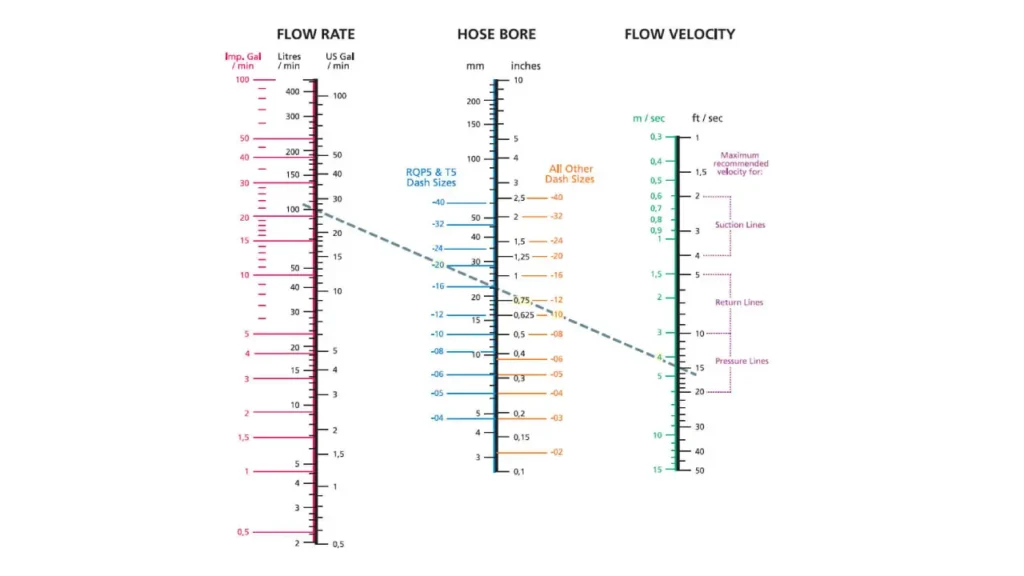
Hydraulic hose manufacturers often provide flow capacity nomographs to help select the appropriate hose size for a given flow rate and pressure. These nomographs are graphical tools that allow you to determine the required hose size based on these factors.
How to Use a Flow Capacity Nomograph:
- Determine Flow Rate: Calculate the required flow rate for your application.
- Select Desired Velocity: Choose a suitable velocity for your application. Higher velocities can increase pressure drop but allow for smaller hose sizes.
- Use the Nomograph: Locate the intersection of the flow rate and velocity lines on the nomograph. The corresponding hose size is the recommended size.
Additional Considerations:
- Safety Factor: It’s recommended to select a hose size slightly larger than the calculated minimum to account for potential variations in flow rate and pressure.
- Hose Material: The material of the hose can also influence flow capacity. Some materials may have higher friction than others, affecting flow.
- Installation: Proper installation, including avoiding excessive bends and ensuring correct fittings, is crucial for optimal flow.
By carefully considering these factors and using flow capacity nomographs, you can select the appropriate hydraulic hose to ensure efficient and reliable fluid flow in your system.
Final Thoughts
This is all about the hydraulic hose flow rate, and it’s much more difficult to work out the result by yourself. No worries, we have an experienced expert to help your select the most suitable hydraulic hose for your hydraulic project.
Please feel free to contact us to get your desired hydraulic hose for your hydraulic system.


