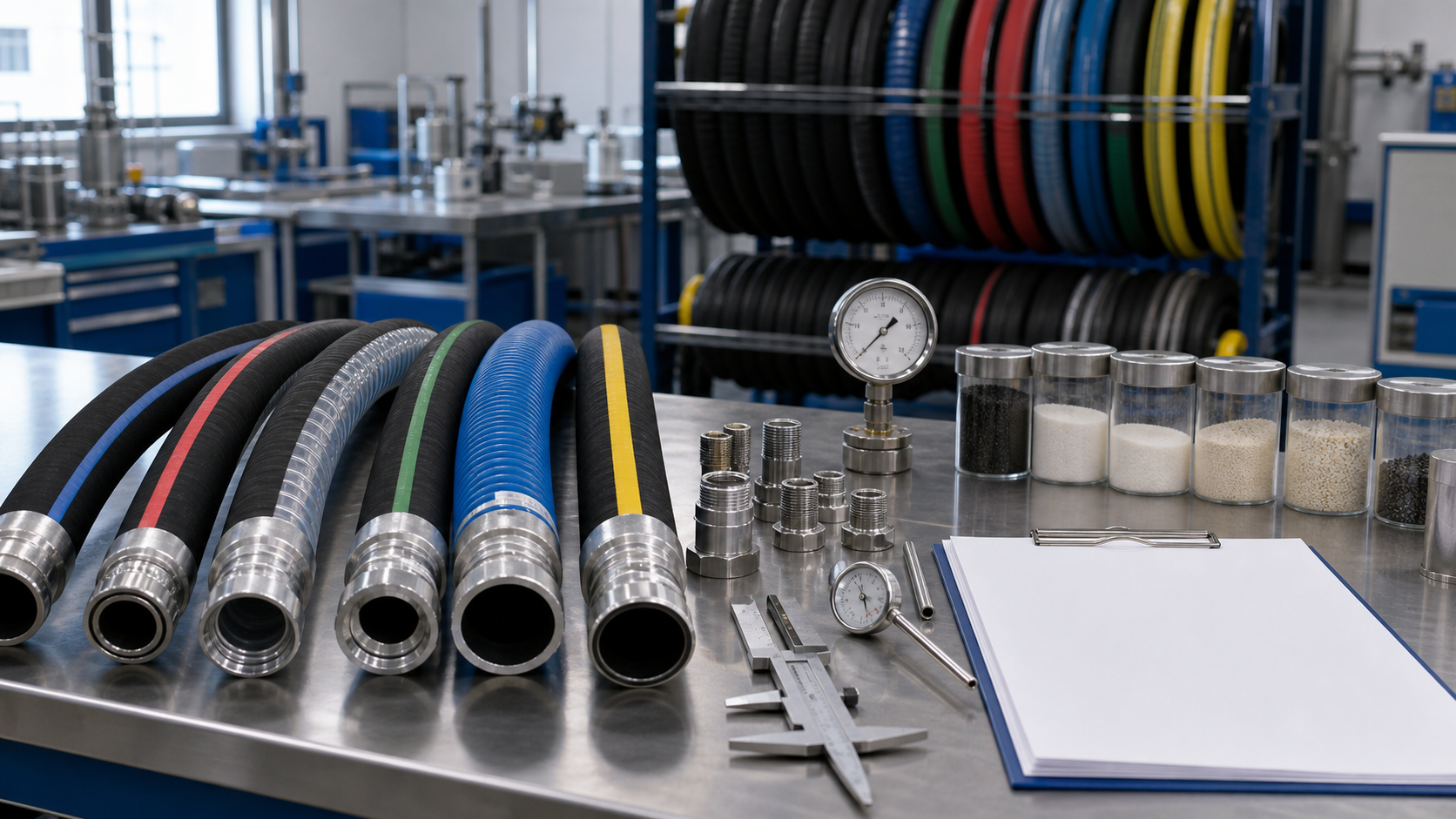
Hydraulic hose assemblies often use elbows at one or both ends to fit crowded equipment. When two bent fittings are installed on the same hose, their angular relationship—commonly called clocking or orientation—must match the machine. A small orientation error can force the installer to twist the hose, tighten a bend, or add an unnecessary adapter.
Correct hydraulic hose fitting orientation is therefore a functional requirement, not a cosmetic detail. OEM drawings, supplier quotations, assembly instructions, and inspection records should define exactly how the angle is measured and tolerated.
What Fitting Clocking Means
Imagine looking along the centerline of a hose from one end. One angled fitting is treated as the reference, and the second fitting is rotated around the hose axis. The angular difference between them is the clocking angle.
Depending on the drawing convention, the reference may be described in degrees or by clock-face positions. Degrees are usually more precise for manufacturing. The drawing must also state the viewing direction; otherwise the same assembly can appear clockwise from one end and counterclockwise from the other.
Straight fittings do not establish a visible rotational direction. If one end is straight and the other is bent, the bent fitting may be oriented relative to a machine feature, label, or drawing datum instead.
Why Incorrect Orientation Causes Damage
An assembly with incorrect clocking may still connect if the installer rotates one end. That rotation is transmitted into the hose body and reinforcement. The hose is designed to flex, but not to operate under continuous torsion.
Twist can:
- Reduce flexibility and impulse life
- Tighten one side of a bend
- Cause the hose to bow out of its intended route
- Increase load on fittings and adapters
- Promote hose-to-hose or hose-to-frame abrasion
- Move a protective sleeve away from the hazard
- Create kinking during machine articulation
Guidance on preventing hose twist should be applied during both assembly production and equipment installation.
Define a Clear Drawing Convention
An orientation note is useful only when every party interprets it the same way.
| Drawing item | What to specify |
|---|---|
| Reference end | End A or the named machine connection |
| Viewing direction | Looking from End A toward End B |
| Rotation direction | Clockwise or counterclockwise |
| Nominal angle | Required angle in degrees |
| Tolerance | Permitted positive and negative variation |
| Fitting datum | Centerline or flat used for measurement |
A drawing should show both fittings, identify End A and End B, and provide a graphical orientation view. Avoid relying only on an ambiguous note such as “90 degrees apart.”
Measure the Correct Datum
Different elbow fittings provide different reference features. A 90-degree elbow can normally be measured along its outlet centerline. A flange may use the flange face, bolt-hole pattern, or bend direction. A fitting with a hex body should not automatically use a hex flat if the outlet centerline is the functional datum.
Agree on the datum before production. The measurement fixture should hold the assembly without bending or twisting it. If the hose is coiled tightly during inspection, elastic forces can change the apparent angle.
The selected hydraulic hose end fittings also need correct connection standards, sealing surfaces, materials, and pressure ratings. Orientation does not compensate for an incorrect fitting type.
Account for Crimping and Springback
During assembly, the hose and fittings may rotate slightly as components are inserted, positioned, and crimped. A supplier should establish a repeatable process that anticipates normal movement rather than correcting every assembly by twisting it afterward.
Production controls can include:
- Marking the hose and fitting reference positions before crimping.
- Using an orientation fixture or digital angle tool.
- Supporting long assemblies so their weight does not rotate a fitting.
- Rechecking clocking after both ends are crimped.
- Recording nonconforming angles and corrective action.
Operators should never rotate a crimped fitting inside the hose to improve clocking unless the approved fitting system explicitly permits an engineered live-swivel function. Most crimped connections are fixed.
Set a Realistic Tolerance
The appropriate tolerance depends on hose length, fitting geometry, connection clearance, routing space, and machine sensitivity. A short assembly between rigid ports may require tighter control than a long hose with a broad flexible route.
An unnecessarily tight tolerance increases inspection and rejection cost. An overly wide tolerance transfers problems to the installer. OEM and supplier should review physical fit and choose a tolerance based on function.
Prototype assemblies can reveal whether a proposed tolerance allows clean installation without torsion. Use the same hose construction intended for production because stiffness and springback vary.
Installation Without Torsion
Correctly manufactured clocking can still be lost through poor installation. Connect one end loosely, route the hose naturally, align the second fitting, and tighten connections using the equipment manufacturer’s sequence. Use backup wrenches where required so tightening torque does not rotate the hose.
The layline is a useful visual indicator. It should follow the hose without spiraling unexpectedly. A twisted layline or a hose that tries to roll after connection signals a problem.
Follow established hydraulic hose routing practices: maintain minimum bend radius, leave a straight section near fittings, allow controlled movement, and prevent contact throughout the machine cycle.
Swivels Are Not a Universal Fix
A swivel adapter can make installation easier, but it adds cost, length, potential restriction, and another leak point. Many swivel fittings are intended for alignment during installation, not continuous rotation under pressure.
If the application rotates repeatedly, use a connection designed and rated as a rotary joint. Do not expect added slack or an ordinary swivel to absorb unlimited torsion.
Inspection and Acceptance
Inspect fitting identity, orientation, assembly length, crimp dimensions, cleanliness, and protection together. A clocking gauge or fixture can improve repeatability for high-volume parts.
An inspection record may include:
- Assembly part number and revision
- Hose and fitting lot identification
- Measured clocking angle
- Required tolerance
- Overall length
- Inspector and date
- Disposition of any nonconformance
Visual comparison with an approved master sample is useful but should not replace dimensional criteria.
Common Communication Failures
Problems often begin with a photograph instead of a drawing, missing viewing direction, undefined End A, no angle tolerance, or inconsistent clockwise conventions between customer and supplier. Another common mistake is copying a used assembly that has already been twisted in service.
Basic hose assembly basics should be documented in the purchase specification so future replacement orders reproduce the approved design.
RFQ Information
Provide hose product and size, cut or overall length, both fitting part numbers, End A and End B, viewing direction, nominal angle, tolerance, protective sleeve position, cleaning, marking, pressure-test requirement, drawing revision, and order quantity.
For complex assemblies, request a first article before volume production. Install it on representative equipment and confirm routing through the full operating range.
Final Principles
Fitting clocking controls how a hose occupies space and carries movement. A correct angle reduces torsion, protects bend radius, and makes installation repeatable.
Clear drawing conventions, suitable fixtures, post-crimp inspection, and careful installation prevent twisted assemblies more reliably than field correction or added adapters.