Wind turbines use hydraulic power for safety-critical and control functions, most commonly blade pitch actuation and mechanical braking. These circuits may remain idle for long periods, respond immediately during a stop command, or cycle repeatedly as operating conditions change. They work inside confined nacelles and hubs where access is difficult and maintenance delays are expensive.
Selecting a wind turbine hydraulic hose requires more than confirming system pressure. Engineers and purchasing teams must account for pressure impulse, low-temperature flexibility, heat, vibration, ozone, oil compatibility, electrical considerations, routing, cleanliness, and long-term reliability. The hose, fittings, and assembly process must be treated as one validated system.
Hydraulic Functions in a Wind Turbine
Hydraulic pitch systems rotate the blades around their longitudinal axes. Pitch control regulates aerodynamic power and can move the blades toward a safe position during shutdown or an emergency. Accumulators may store energy so that the system can complete a safety movement if electrical power is lost.
Hydraulic brake circuits apply or release mechanical brakes on the drivetrain or rotor, depending on the turbine design. Other hydraulic functions can include rotor locking, yaw braking, service tools, and maintenance equipment.
Each hose location has its own duty:
- Pump outlet and accumulator charging lines face high pressure and cycling.
- Cylinder lines move with pitch actuators and may flex repeatedly.
- Brake lines must hold pressure reliably and respond predictably.
- Return and drain lines require low restriction and correct oil compatibility.
- Service hoses may be connected intermittently but still need controlled cleanliness.
The specification should identify the function and consequence of failure for every assembly.
Pressure, Stored Energy, and Impulse Duty
Pitch and brake systems can contain stored hydraulic energy. A hose may remain pressurized while the turbine is stopped, and transient loads can occur during valve switching or emergency actuation. The selected high-pressure hose must cover the maximum continuous pressure and credible peaks for its size and temperature.
Burst pressure is not a design pressure. Compare rated working pressure, proof pressure, impulse performance, minimum bend radius, and any temperature derating. For circuits that cycle frequently, request impulse data under conditions representative of the application.
Pressure pulsation can also affect fittings and support points. A hose that moves visibly with every cycle may have excessive unsupported length, poor routing, or inadequate restraint. Clamps should control motion without crushing the cover or concentrating bending at the coupling.
Rubber or Thermoplastic Construction?
Both rubber and thermoplastic hoses can serve wind-energy applications when their constructions are properly qualified. The correct choice depends on pressure, temperature, movement, fluid, routing space, permeation, and service requirements.
A thermoplastic hydraulic hose can offer compact dimensions, low weight, long continuous lengths, and useful low-temperature or chemical characteristics in selected constructions. These features can be valuable in hub and nacelle routing. Thermoplastic hoses also have specific bend, fitting, and permeation behavior that must be considered.
Rubber hose may provide robust flexibility and vibration resistance. Wire-braided or wire-spiral reinforcement can support higher-pressure duties, but added reinforcement affects weight and bend radius. Material-family labels alone are insufficient; approval must refer to the full hose specification.
Temperature Across the Turbine Environment
A turbine may experience cold starts in winter, high nacelle temperatures during summer operation, and repeated thermal cycling. Low temperature can stiffen hose materials, raise oil viscosity, and increase the force required for bending. High temperature accelerates elastomer aging and can reduce pressure capability.
Record minimum startup temperature, normal fluid temperature, maximum fluid temperature, and local ambient temperature. The hub, nacelle, and tower base may not share the same conditions. Heat near gearboxes, generators, converters, or braking equipment should be evaluated at the hose location rather than inferred from outdoor air temperature.
If heaters are used to condition hydraulic oil, consider the hose conditions before the fluid reaches its target temperature. A system that functions after warm-up may still impose severe loads during the first movement.
Vibration, Flexing, and Routing
Turbines generate continuous vibration and structural movement. Pitch hoses may move with blades and cylinders, while nacelle hoses can be affected by drivetrain vibration and yaw movement. Poor routing converts this motion into abrasion, twist, or repeated bending at the fitting.
Observe the complete operating envelope. The hose must remain above its minimum bend radius, avoid tension at maximum movement, and retain enough controlled slack without contacting surrounding structures. Keep the first bend away from the ferrule and use the hose layline to identify twist.
Where a route crosses an edge or passes through a panel, use a smooth guide or suitable guard. Clamps should support the assembly but permit the movement required by the design. Cable ties alone may create concentrated pressure points and are rarely a substitute for engineered supports.
Ozone, UV, Moisture, and External Exposure
Hoses inside the nacelle may still encounter ozone, condensation, oil mist, cleaning products, and temperature cycling. Components in the hub or exposed service areas can also face moisture and UV. Offshore turbines add salt-laden air and a more aggressive corrosion environment.
Review the cover material, fitting finish, clamps, and adjacent metals. Moisture that reaches exposed steel reinforcement through a damaged cover can promote corrosion. Protective sleeves should resist the actual exposure and should not conceal leaks or trap water.
For offshore installations, corrosion control should cover the full assembly and its supports, not just the hose fitting. Material combinations should also avoid unnecessary galvanic corrosion risk.
Fluid Compatibility and Permeation
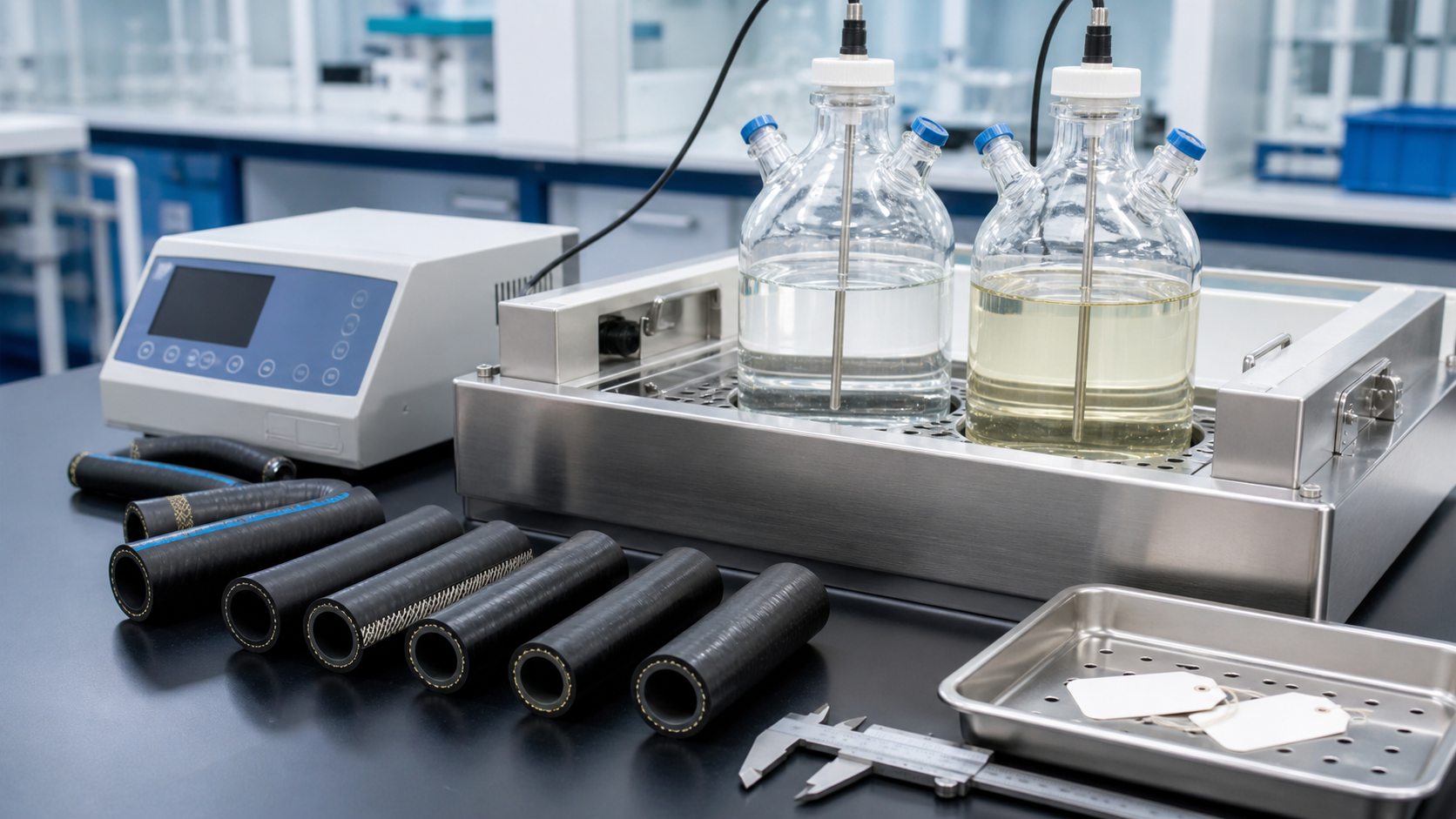
Provide the exact hydraulic fluid name when requesting approval. Mineral, synthetic, biodegradable, and fire-resistant fluids can interact differently with tube and seal materials. Compatibility must account for maximum temperature and expected exposure time.
Permeation may matter inside an enclosed nacelle or hub. It can contribute to odor, surface wetness, fluid loss, or cover changes even when no conventional leak is visible. Ask whether the proposed tube construction has relevant permeation data or field history.
O-rings, accumulator bladders, valve seals, and fitting seals must also be compatible. Approving the hose tube alone does not validate the complete fluid path.
Fittings, Cleanliness, and Assembly Quality
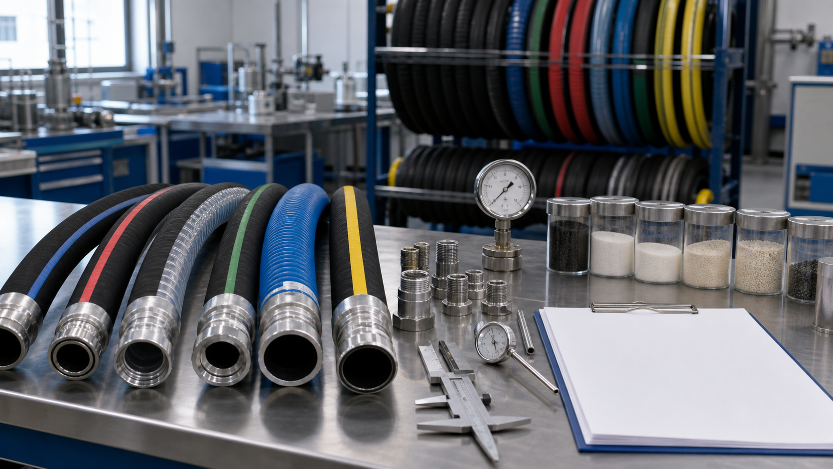
Use hydraulic hose fittings approved for the chosen hose, together with the specified ferrule and crimp diameter. Unvalidated mixing can damage the tube, reduce retention, or create leakage.
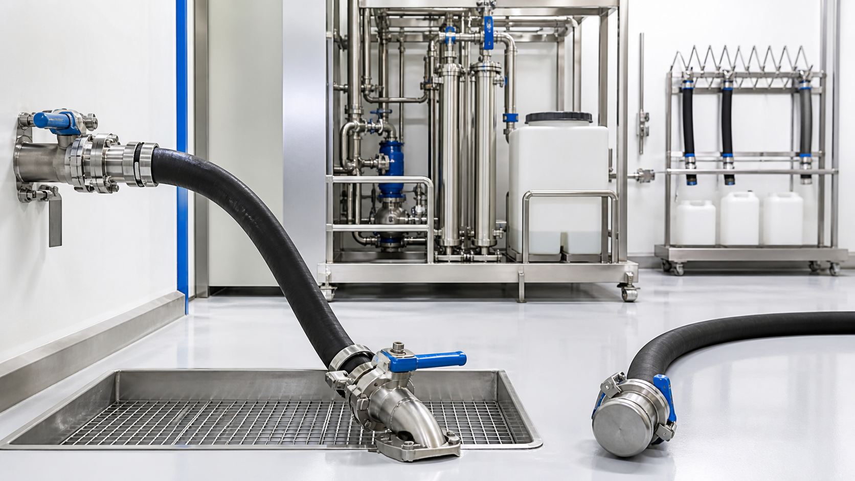
Wind-turbine hydraulic systems often use proportional valves and other contamination-sensitive components. Specify hose cleaning, particle-removal verification where required, end capping, and clean packaging. Keep caps in place until installation.
For angled fittings, document rotational orientation. Also control hose length because even a small error can alter bend radius or create contact in a compact hub. Traceable assembly marking can record part number, manufacturer, batch, and production date without compromising bend zones.
When Custom Assemblies Are Appropriate
Standard hose products can be manufactured into project-specific assemblies. Custom hydraulic hoses may combine controlled length, special fitting orientation, protective sleeves, cleanliness requirements, identification, pressure testing, and packaging for a particular turbine position.
Customization should not mean an undocumented one-off solution. Define drawings, approved materials, tolerances, tests, change control, and replacement part numbers. For multi-year turbine programs, preserving the approved assembly specification is essential when components or suppliers change.
Inspection and Service Planning
Turbine access is costly, so hose inspection should be integrated into planned maintenance. Examine assemblies for abrasion, cracks, hardening, blistering, leaks, corrosion, fitting movement, twisting, tight bends, and damaged guards. Inspect clamps and adjacent structures as well.
Depressurize stored-energy systems according to the turbine manufacturer’s procedure before service. Accumulators can keep a circuit dangerous after the pump is stopped. Never use a hand to locate a suspected pinhole leak.
Track installation date, operating hours, turbine position, inspection findings, and removed-hose condition. Condition data from multiple turbines can reveal whether failures relate to age, routing, batch, climate, or a particular duty cycle.
Information Required for an RFQ
Provide the turbine model, circuit function, safety classification, hose bore and length, continuous and peak pressure, impulse duty, fluid, internal and ambient temperature range, movement, minimum bend radius, cover exposure, fitting standard, orientation, cleanliness, testing, marking, traceability, packaging, and annual volume.
For replacements, drawings and approved bills of material are preferable to copying a weathered field assembly. Any proposed substitution should be reviewed against the original requirements rather than accepted because it fits physically.
Final Selection Principles
Reliable wind turbine hoses combine pressure capacity with stable performance through cold, heat, vibration, movement, and long service intervals. The best construction is the one validated for the exact fluid, circuit, environment, fittings, and maintenance strategy.
By defining these conditions clearly and controlling assembly quality, turbine OEMs and operators can reduce avoidable leaks, simplify replacement sourcing, and support the dependable operation of pitch and brake systems.