Abrasive blasting moves dry particles and compressed air at high velocity. Friction between abrasive, air, hose tube, nozzle, and workpiece can generate static electricity. If charge cannot dissipate through a controlled path, an operator may receive shocks, equipment may be damaged, or an ignition hazard may develop where combustible dust or vapor is present.
Safe sandblast hose grounding and conductivity require more than choosing a black rubber hose. Hose construction, couplings, nozzle holder, bonding connections, compressor system, workpiece, PPE, inspection, and operating procedure must work together.
Safety note: Abrasive blasting can expose workers to high pressure, respiratory hazards, noise, flying particles, static discharge, and hose whip. Follow the site’s risk assessment, equipment instructions, regulations, and qualified safety guidance.
Why Static Develops
As abrasive particles travel through the hose, repeated contact and separation can transfer electrical charge. Charging tendency depends on abrasive type, dryness, velocity, humidity, hose materials, line length, nozzle, and equipment configuration.
Low humidity and dry abrasive can allow charge to persist. Long hose runs and high production rates increase the amount of contact. Insulating surfaces may prevent charge from reaching earth, while isolated metal components can develop a different electrical potential.
Static shock is a warning, not a normal condition to tolerate. The cause should be investigated before work continues.
Conductive Hose vs a Complete Grounding Path
A properly designed sandblasting hose may use a conductive inner tube, conductive compound, embedded wire, or another path intended to dissipate charge. But the hose alone cannot guarantee that the entire blasting system is grounded.
| Element | What must be confirmed |
|---|---|
| Hose | Specified electrical performance and abrasion rating |
| Couplings | Conductive connection to the hose path |
| Nozzle holder | Correct material, fit, and continuity |
| Blast nozzle | Compatible, secure, and electrically connected as designed |
| Blast pot/system | Bonded and grounded per engineered procedure |
| Workpiece | Bonded or grounded when required |
| Ground point | Approved and verified—not assumed |
A metal fitting touching rubber does not automatically create continuity. Paint, corrosion, dirt, gaskets, thread sealant, and poor assembly can interrupt the path.
Specify Electrical Performance
“Anti-static” is too vague for an RFQ. Define the required resistance or conductivity classification, measurement points, test method, acceptance limit, environmental conditions, and inspection frequency.
Requirements may differ by industry, abrasive, equipment, and hazardous-area classification. Do not copy a resistance value from an unrelated fuel or pneumatic hose application.
Ask the supplier whether electrical performance is provided through the tube, cover, wire, or entire coupling-to-coupling assembly. Confirm whether the hose must be tested after fittings are installed.
Bond and Ground the System
Bonding connects conductive components so dangerous potential differences are less likely. Grounding connects the bonded system to an approved earth reference. The facility should identify designated connection points and suitable conductors.
Ground clips need clean metal contact, adequate force, protected cables, and regular inspection. Do not attach to painted frames, rusty surfaces, uncertain building steel, or random piping and assume the connection is effective.
The blasting machine, hose assembly, nozzle components, workpiece, recovery equipment, and dust collection system may all require consideration. A qualified person should review the complete path, especially where combustible dust, vapor, tanks, or enclosed spaces are involved.
Select the Hose for Abrasion as Well as Conductivity
Electrical performance does not compensate for a weak tube. Abrasive particles erode the bore continuously, particularly at bends. Select hose inside diameter, wall thickness, tube compound, reinforcement, working pressure, cover, and bend radius for the abrasive and duty.
Provide suppliers with abrasive type, particle size and shape, moisture content, flow rate, air pressure, hose length, bend layout, expected hours, temperature, and external environment. Sharp angular media can wear differently from round media.
Review typical sandblast hose applications but base the final choice on the actual process. Heavy stationary blasting, portable maintenance, shipyard work, and blast rooms can require different constructions.
Size the Hose Correctly
An undersized hose increases pressure loss and may reduce nozzle performance. Operators may raise compressor pressure to compensate, increasing energy use and stress. A hose that is too large is heavier and harder to handle.
Match bore to nozzle, required airflow, total length, fittings, and compressor capacity. Avoid unnecessary reducers. Keep routing smooth and use the minimum practical length without creating tension.
The sandblast hose and nozzle should be treated as one system. A worn nozzle increases air and abrasive consumption and can change performance even when the hose is unchanged.
Assemble Couplings and Nozzle Holders Correctly
Use components intended for the exact hose outside diameter and wall. Follow insertion, screw, pin, gasket, and retention instructions. Incorrect size can damage reinforcement, loosen during operation, or break the conductive path.
Install safety pins, clips, whip checks, or restraints where specified. These are secondary controls, not substitutes for a secure coupling. Confirm gasket condition and alignment so leakage does not erode the connection.
After assembly, perform required pressure, retention, and electrical checks. Record hose identification and measured continuity where the inspection plan requires it.
Route to Reduce Wear and Risk
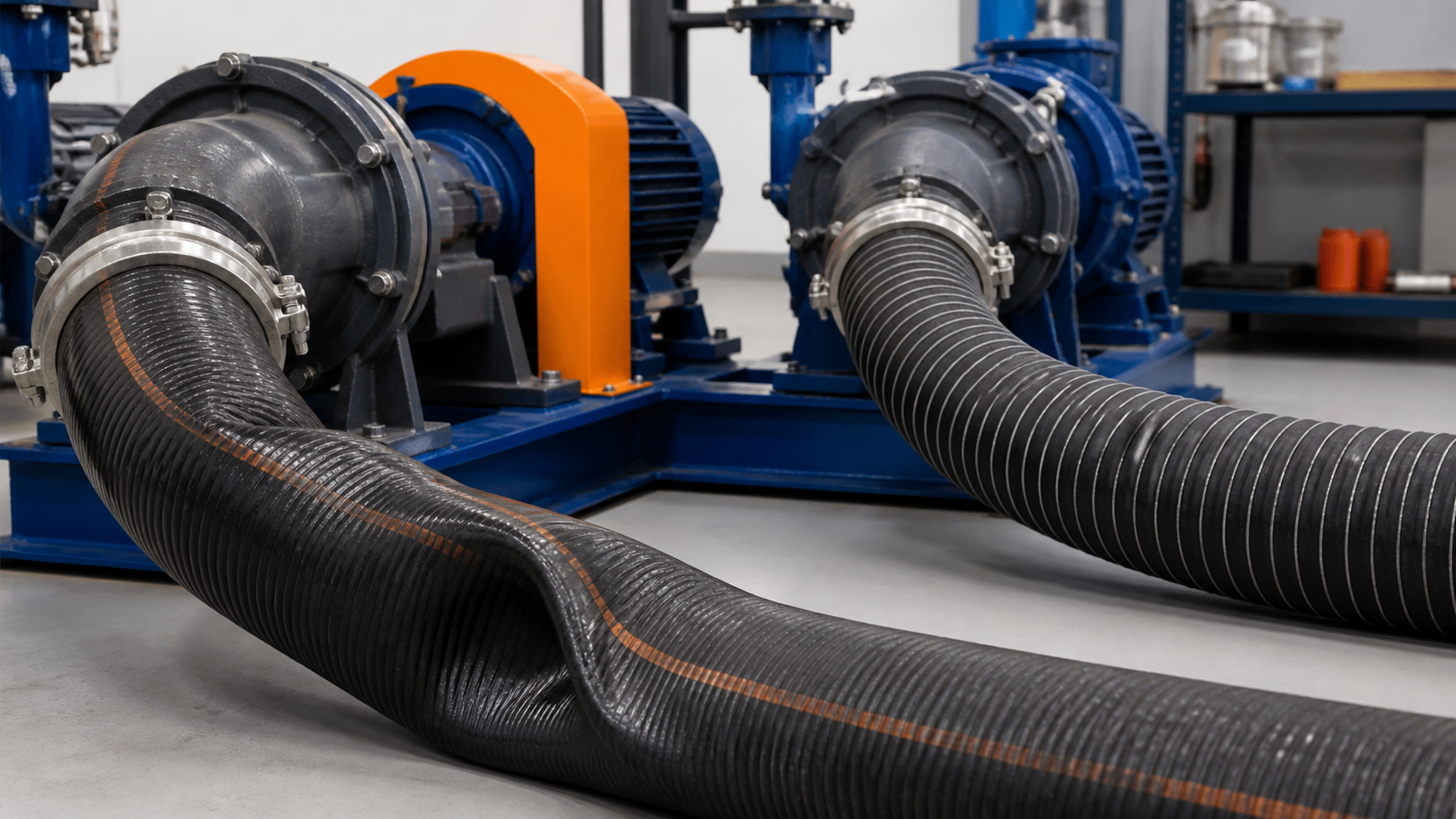
Bends concentrate abrasive impact on the outer radius. Tight bends, kinks, and loops accelerate wear and can reduce airflow. Route the hose with broad curves, support heavy sections, and prevent vehicle traffic or crushing.
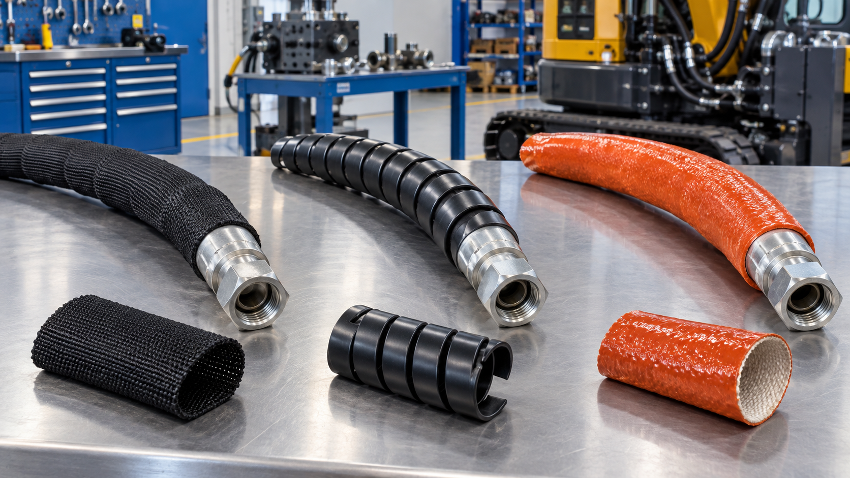
Avoid dragging over sharp steel, concrete edges, hot surfaces, or standing water. Use protective ramps or sleeves where external abrasion cannot be eliminated, but keep inspection areas visible.
Do not attach the hose so rigidly that movement loads the coupling. Provide controlled slack without creating trip hazards or low loops that are repeatedly run over.
Inspect Before Every Use
Check the full length, not only the ends. Look for:
- soft spots, bulges, flattening, and kinks;
- cover cuts, cracks, and exposed reinforcement;
- localized wear at bends and contact points;
- loose couplings or nozzle holders;
- missing screws, safety pins, or restraints;
- damaged grounding cables and clamps;
- evidence of arcing, heat, or repeated shocks;
- illegible identification or expired inspection status.
Depressurize and isolate the system before detailed inspection. Never feel for leaks with a hand while the line is energized.
Measure Wear Systematically
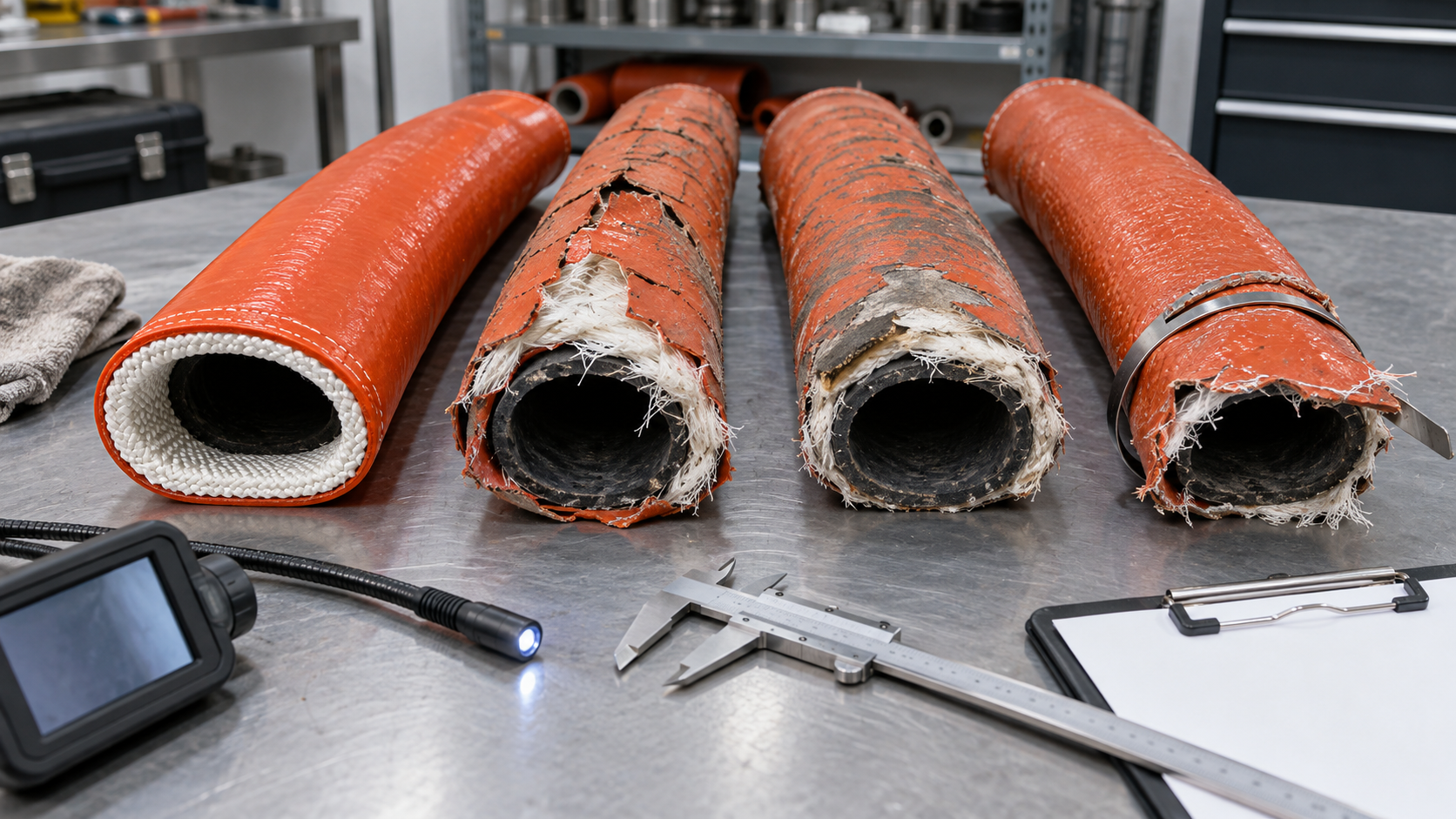
External appearance may not reveal tube erosion. Use an approved wall-thickness or bore-inspection method at defined locations, especially bends and the nozzle end. Establish baseline measurements on new hose and trend the results.
Rotate hose only if the manufacturer and site procedure permit it; rotation can redistribute wear but may also move a weakened section into a new stress position. Never use rotation to extend a hose beyond its rejection limit.
Review when to replace a sandblast hose and define site-specific rejection criteria before the hose becomes critical.
Operator PPE and Work Practices
Grounding is only one safety control. Operators need an approved blasting helmet or respirator system, supplied breathing air where required, hearing protection, protective clothing, gloves, and footwear suitable for the hazard assessment.
Confirm deadman control function, communication, visibility, exclusion zones, ventilation, dust collection, and emergency shutdown. Inspect breathing-air equipment separately from blast-air equipment.
If operators report shocks, stop and investigate continuity, grounding, humidity, abrasive, PPE, and system changes. Do not normalize the symptom or improvise a loose wire around the hose.
Replacement and Incident Review
Remove an assembly from service after failed continuity, excessive wear, damaged reinforcement, permanent kinking, coupling movement, fire or heat exposure, crushing, severe impact, or an unexplained static event.
Record the location and failure mode. If multiple hoses wear at the same point, change routing or support. If continuity drifts, investigate fitting contact, corrosion, wire fatigue, and test method.
Final Safety Principle
A conductive sandblast hose is an engineered component in a larger electrical and pressure system. Its protection depends on correct fitting installation, verified continuity, bonding, grounding, controlled routing, inspection, and trained operators.
Specify the electrical path, test it after assembly, and monitor it through service. Combined with abrasion management and proper PPE, that discipline reduces shocks, unexpected failures, and uncontrolled releases.