Every time a 50-ton excavator lifts its bucket, a commercial aircraft retracts its landing gear, or a hydraulic press stamps out a metal part in under a second — a hydraulic system is doing the work. These systems are so deeply embedded in modern industry that we rarely stop to think about how they function, or why they’re chosen over electric motors and pneumatic systems for so many critical applications.
This guide answers those questions in full. Whether you’re an engineer specifying hoses for a new machine, a procurement manager evaluating suppliers, or a technician trying to understand why a system failed, you’ll find the technical grounding you need here — along with practical guidance on where hydraulic hoses fit into the picture.
What is a Hydraulic System?

A hydraulic system is a power transmission technology that uses pressurized, incompressible liquid — most commonly hydraulic oil — to generate, control, and deliver mechanical force and motion.
The fundamental principle was formalized by French mathematician Blaise Pascal in the mid-1600s, and it remains the foundation of every hydraulic circuit built today: pressure applied to a confined fluid transmits equally in all directions. This means a small input force applied over a small area can generate an enormously larger output force over a larger area — the principle behind the mechanical advantage that makes hydraulics so valuable for heavy-duty work.
In practical terms: a hydraulic pump pressurizes fluid, which travels through hoses and valves to reach actuators (cylinders or motors), which convert that fluid pressure back into mechanical motion — lifting, pushing, rotating, or pressing with forces that would be impractical or impossible to achieve through direct mechanical linkages.
Why incompressible fluid matters: Unlike air (which compresses under pressure and gives pneumatic systems their characteristic “springiness”), hydraulic oil transmits force almost instantaneously and with no energy loss to compression. This is what gives hydraulic systems their characteristic precision, stiffness, and power density.
Core Components of a Hydraulic System
A hydraulic circuit consists of interconnected components, each serving a defined function. Understanding what each part does — and how it can fail — is essential for anyone specifying, operating, or maintaining hydraulic equipment.
Hydraulic Pump
The pump is the heart of the system. It draws hydraulic fluid from the reservoir and pressurizes it, converting mechanical energy (from an electric motor or combustion engine) into hydraulic energy. It does not create pressure itself — pressure is a consequence of resistance downstream. If the system’s actuator is stalled against a load, pressure rises; if it moves freely, pressure remains low.
The three main pump types used in industrial and mobile hydraulic systems are:
- Gear pumps — simple, robust, and economical. Fixed displacement. Best suited for medium-pressure applications with relatively clean fluid. Common in agricultural equipment and simple industrial circuits.
- Vane pumps — quieter and smoother than gear pumps, with good efficiency across a range of pressures. Used in machine tools and industrial presses.
- Piston pumps — the choice for high-pressure, high-efficiency applications. Available in fixed and variable displacement configurations. Standard in excavators, heavy machinery, and precision industrial systems.
Hydraulic Reservoir
More than just a tank, the reservoir performs several critical functions: storing fluid for the system’s operational needs, dissipating heat through its metal walls, allowing entrained air bubbles to separate and escape, and providing space for fluid volume changes as cylinders extend and retract. Proper reservoir sizing — typically two to three times the pump’s per-minute flow rate — is essential for thermal management and system health.
Valves
Valves are the control architecture of a hydraulic circuit. They determine where fluid flows, how fast it flows, and at what pressure. Three primary valve types govern every hydraulic system:
- Directional control valves — route fluid to specific actuators and determine the direction of movement (extend/retract, clockwise/counterclockwise). The most visible control point for the machine operator.
- Pressure relief valves — the system’s safety mechanism. Set to open at a defined maximum pressure, they divert fluid back to the reservoir if pressure exceeds the safe limit, protecting pumps, hoses, and cylinders from damage.
- Flow control valves — regulate the speed of actuator movement by restricting or metering fluid flow. Precise flow control enables smooth, predictable machine behavior.
Actuators
Actuators are where hydraulic energy converts back into mechanical work. There are two fundamental types:
- Hydraulic cylinders — produce linear (straight-line) motion. A piston inside the cylinder is pushed by pressurized fluid, extending or retracting a rod. Used for lifting, clamping, pressing, tilting, and pushing. A compact cylinder can generate tens or hundreds of tonnes of force.
- Hydraulic motors — produce rotary motion. Fluid pressure acts on pistons, vanes, or gears to spin an output shaft. Used in winches, conveyors, wheel drive systems, and drilling equipment.
Hydraulic Fluid
The fluid is both the energy carrier and the lubricant for the entire system. Standard mineral hydraulic oils dominate industrial and mobile applications, chosen for their viscosity stability, oxidation resistance, and wear protection properties. Specialty fluids — water-glycol, phosphate ester, biodegradable synthetic esters — are used where fire resistance or environmental sensitivity is required.
Fluid contamination is consistently identified as the leading cause of hydraulic system failure. Particles as small as 10–15 microns can damage pump internals, score valve spools, and accelerate seal wear. Maintaining proper filtration and regular fluid condition monitoring is not optional maintenance — it is the primary predictor of system lifespan.
Hydraulic Hoses, Tubes, and Fittings
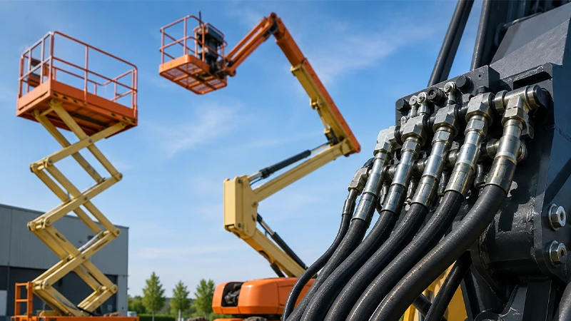
Hoses, tubes, and rigid piping form the circulatory network that connects all other components, routing pressurized fluid from pump to valve to actuator and back. In mobile equipment — excavators, agricultural machinery, lifting platforms — hydraulic hoses handle the connections between components that move relative to each other, absorbing vibration, accommodating articulation, and routing around obstacles that rigid piping cannot navigate.
For a detailed look at how hydraulic hoses are classified and selected, see the section below.
Filters and Heat Exchangers
Filters protect the system from particulate contamination, capturing wear debris, ingressed dirt, and oxidation byproducts before they can damage precision components. Hydraulic oil coolers — either air-blast or water-cooled — manage the system’s thermal load, preventing fluid viscosity breakdown and seal degradation from heat buildup.

How a Hydraulic System Works: The Complete Cycle
Understanding the system as a continuous loop, rather than a series of separate events, is the key to diagnosing problems and optimizing performance.
1. Fluid Pressurization The pump draws fluid from the reservoir and pushes it into the system under pressure. The pressure level is not set by the pump — it is determined by the load on the actuator and constrained by the pressure relief valve setting.
2. Flow Routing Through Valves Pressurized fluid reaches the directional control valve. In neutral position, fluid may recirculate (open-center system) or be held at pressure (closed-center system). When the operator activates a function, the valve spool shifts, directing flow to the appropriate actuator port.
3. Actuator Operation Fluid pressure acts on the actuator — pushing a cylinder piston or spinning a hydraulic motor. The actuator converts hydraulic energy into mechanical work: lifting, rotating, pressing, or pulling the connected load.
4. Return Flow After doing work, the fluid returns from the actuator’s exhaust port through the directional valve, passes through the return filter, and flows back to the reservoir — where it cools, releases entrained air, and awaits the next cycle.
5. Continuous Loop This cycle repeats continuously while the system is running. In a well-designed, properly maintained system, this loop operates seamlessly for thousands of hours. Disruption anywhere in the loop — contamination, heat buildup, hose failure, seal degradation — propagates throughout the entire circuit.
Types of Hydraulic Systems
Not all hydraulic circuits are structured the same way. The two fundamental circuit architectures differ in how they manage fluid flow when actuators are idle.
Open-Center Systems
In an open-center system, the control valve’s neutral position has an open flow path directly back to the tank. The pump runs continuously, circulating fluid through the system even when no work is being done. Only when the operator activates a valve does fluid divert to the actuator.
Advantages: Simpler design, lower initial cost, uses inexpensive fixed-displacement gear pumps. Easy to diagnose and maintain.
Disadvantages: Fluid circulates at constant flow even when idle, generating heat and wasting energy. Power output is less flexible. Less suitable for applications requiring simultaneous, independent control of multiple functions.
Typical applications: Older agricultural tractors, simple dump trucks, forestry equipment, basic industrial machines.
Closed-Center Systems
In a closed-center system, the control valve is closed in neutral, and the pump is pressure-compensated — it reduces output to near-zero flow when no actuator is demanding work, but maintains the system at full standby pressure. When a valve is activated, the pump responds immediately to the demand.
Advantages: Significantly more energy-efficient, especially in applications with long idle periods. Less heat generation. Single pump can supply multiple independent functions simultaneously. Better suited to precise, complex control.
Disadvantages: More complex and expensive — requires a variable-displacement pump and load-sensing circuitry. Requires cleaner fluid and more precise maintenance.
Typical applications: Modern excavators, high-performance agricultural tractors, aerospace hydraulics, precision industrial machinery.
Where Hydraulic Systems Are Used: Key Industries
Hydraulic systems are found wherever the combination of high force, precise control, and compact packaging is non-negotiable.
Construction Equipment This is the dominant application sector for hydraulic systems worldwide. Excavators, wheel loaders, cranes, bulldozers, and concrete pumps all depend on hydraulics to deliver the force required for digging, lifting, and grading. A mid-size excavator’s hydraulic system typically operates at 300–380 bar, powering multiple independent circuits simultaneously through a sophisticated valve stack.
Agriculture Tractors, combines, sprayers, and balers use hydraulic systems for implement control — raising and lowering attachments, adjusting cutting heights, powering PTO-driven equipment, and steering. Modern precision agriculture demands the kind of repeatable, controllable force delivery that only hydraulics provides.
Industrial Manufacturing Hydraulic presses, injection molding machines, metal stamping equipment, and CNC machining centers rely on hydraulics for controlled, high-force clamping, forming, and positioning. The ability to maintain constant force under load — which electric motors cannot do without specialized controls — makes hydraulics indispensable in metalworking and plastics processing.
Automotive Power steering systems, hydraulic brakes, convertible roof mechanisms, and vehicle suspension systems all employ hydraulic circuits. The hydraulic brake system is one of the most compelling demonstrations of Pascal’s principle in everyday life: a modest force on the brake pedal is multiplied through incompressible brake fluid to clamp brake pads against all four wheels simultaneously.
Aerospace and Aviation Aircraft landing gear, flight control surfaces (flaps, spoilers, rudder), cargo door mechanisms, and thrust reverser systems operate hydraulically. Aviation hydraulic systems typically operate at 3,000–5,000 PSI, with newer aircraft pushing toward 5,000 PSI systems for weight savings. Redundancy is built into every circuit — failure of a single hydraulic system cannot result in loss of critical functions.
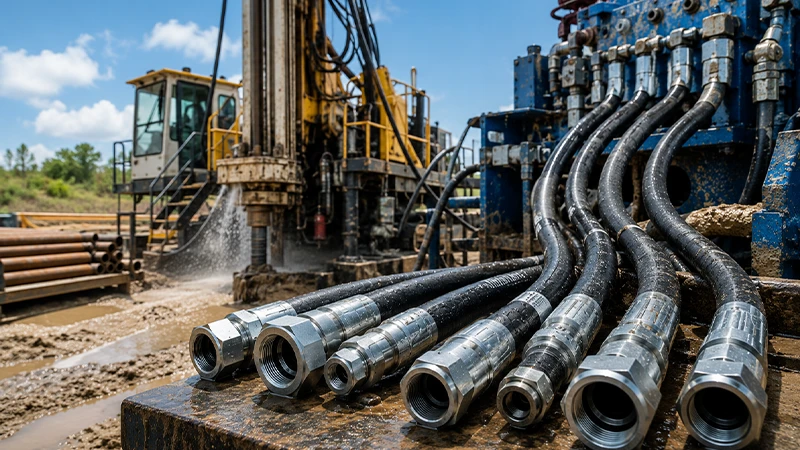
Marine and Offshore Deck cranes, anchor windlasses, steering systems, and offshore drilling rigs all use hydraulic power. The high power density and saltwater resistance of properly designed hydraulic systems make them essential in marine environments where electrical systems would corrode rapidly.
Hydraulics vs. Pneumatics: When to Use Each
A common design decision is whether a given application should be served by hydraulics or pneumatics. The right answer depends on the specific force, speed, precision, and environmental requirements.
| Factor | Hydraulic System | Pneumatic System |
|---|---|---|
| Working Fluid | Incompressible oil or water-based fluid | Compressed air or inert gas |
| Operating Pressure | 70–700+ bar (1,000–10,000+ PSI) | Typically 5–10 bar (70–145 PSI) |
| Force Output | Very high — ideal for heavy loads | Moderate — suited to light/medium loads |
| Speed | Slower, but highly controllable | Fast, responsive — good for rapid cycling |
| Precision | Excellent — fluid incompressibility enables precise positioning | Lower — air compressibility introduces variability |
| Energy Efficiency | High power density; efficient under sustained load | Energy lost to air compression; less efficient |
| Fluid Leakage Risk | Oil leaks are messy, environmentally problematic, and a fire risk | Air leaks are harmless |
| Complexity & Cost | Higher — specialized fluid, seals, filters, coolers | Lower — simpler circuits, standard air supply |
| Best For | Lifting, forming, pressing, heavy equipment | High-speed automation, assembly, light clamping |
Choose hydraulics when: The application demands high force or torque, precise positioning under load, sustained force without creep, or compact packaging for extreme power density.
Choose pneumatics when: Speed and rapid cycling matter more than force, the load is light to medium, environmental contamination from fluid leaks is unacceptable, or simplicity and low cost are priorities.
Hydraulic Hoses: The Critical Link in Every Hydraulic Circuit
Hydraulic hoses are the flexible arteries of a hydraulic system — they carry pressurized fluid between components that must be able to move, vibrate, or articulate relative to each other. In a mobile machine like an excavator, there may be dozens of hose assemblies, each routed precisely to accommodate the machine’s full range of motion without kinking, chafing, or exceeding its minimum bend radius.
Hose Construction
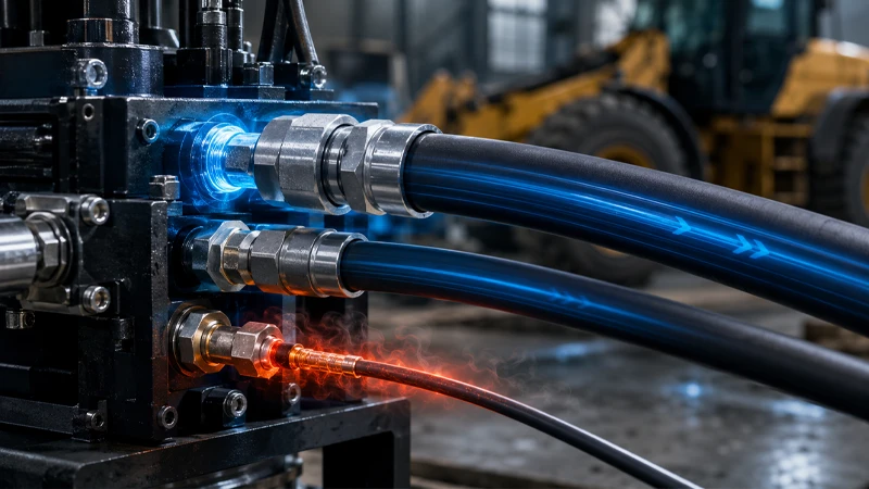
Every hydraulic hose consists of three layers working together:
- Inner tube — carries the hydraulic fluid. Must be chemically compatible with the specific fluid used (mineral oil, water-glycol, synthetic ester, etc.). Typically made from synthetic rubber (NBR, EPDM, or PTFE for aggressive media).
- Reinforcement layer(s) — provides pressure resistance. Wire braid or spiral wire layers carry the hoop stress generated by internal pressure. The number and type of reinforcement layers determines the hose’s pressure rating.
- Outer cover — protects the reinforcement from abrasion, UV, ozone, and environmental chemicals. The cover material and thickness directly affect service life in harsh environments.
Hose Classification: SAE and EN Standards
Hydraulic hoses are manufactured and tested to internationally recognized standards that define pressure ratings, construction requirements, and performance parameters. The most common standards buyers encounter are:
SAE (Society of Automotive Engineers) Standards:
- SAE 100R1AT / R1A — single wire braid. Standard general-purpose hose for moderate pressures.
- SAE 100R2AT / R2A — double wire braid. Higher pressure than R1. The most widely used hydraulic hose type globally.
- SAE 100R4 — suction hose with wire helix reinforcement for vacuum service.
- SAE 100R9 / R12 / R13 / R15 — four-wire spiral construction for very high-pressure applications such as rock breakers and mobile crane circuits.
- SAE 100R7 / R8 — thermoplastic construction. Lightweight, low-friction, used in agricultural and material handling equipment.
- SAE 100R14 — PTFE (Teflon) inner tube for aggressive chemical compatibility and high-temperature service.
EN (European Standard) equivalents are largely cross-compatible with SAE standards: EN853 1SN / 2SN correspond to SAE R1AT / R2AT; EN856 4SP and 4SH correspond to high-pressure spiral hoses.
How to Choose the Right Hydraulic Hose
Selecting the correct hose requires answering five questions — a framework the industry often calls STAMPED:
S — Size: Match the internal diameter (ID) to the required flow rate, keeping fluid velocity within recommended limits (typically 2–4 m/s for pressure lines, under 1 m/s for return lines). Using an undersized hose increases velocity, heat, and pressure drop.
T — Temperature: The hose must handle both the fluid temperature and the ambient temperature. Most standard hydraulic hoses are rated from -40°C to +100°C. Systems with high heat load or those operating near heat sources may require hoses with higher temperature ratings or external heat protection.
A — Application / Environment: Is the hose exposed to abrasion, UV, ozone, or chemical splash? Does it need to flex constantly? Will it be routed near moving parts? Environmental factors determine which outer cover material and which protective measures (spiral guards, fire sleeves) are needed.
M — Media (Fluid Compatibility): Is the fluid mineral oil, water-glycol, phosphate ester, or a biodegradable synthetic? Each fluid type has different compatibility requirements for the inner tube material. Using an incompatible tube causes swelling, delamination, and contamination of the hydraulic system.
P — Pressure: The hose must be rated for the system’s maximum working pressure including pressure spikes. Hydraulic circuits generate pressure pulses — momentary spikes that can be 2–3× the nominal working pressure — during rapid valve actuation. Select hoses with a safety factor (typically 4:1 burst-to-working pressure) that accounts for these spikes.
E — Ends (Fittings): The fitting must match the hose construction (crimp or reusable), the connection standard (BSP, JIC, NPT, SAE, ORFS), and the mating port on the component. Mismatched fittings are a leading cause of leaks and premature hose assembly failure.
D — Delivery (Length and Routing): Route hoses to avoid tight bends below the minimum bend radius, contact with moving parts, and routing that places hoses under tension. Correct routing is as important as correct specification — a well-specified hose that is poorly routed will fail prematurely.
Common Hydraulic System Problems and How to Prevent Them
Fluid Contamination
The single most common cause of hydraulic system failure. Particle contamination accelerates wear on pump internals, valve spools, and actuator seals. Water ingress causes fluid oxidation, corrosion, and loss of lubrication properties. Prevention requires proper filtration (maintained to the system’s target cleanliness class), regular fluid condition monitoring, and rigorous sealing of all reservoir breathers and access points.
Overheating
Hydraulic oil above its optimal temperature range loses viscosity and oxidizes rapidly, shortening fluid and seal service life. Common causes include undersized reservoirs, blocked coolers, excessive back-pressure in return lines, and operation with an open-center pump constantly circulating fluid under load. Thermal management is a design consideration, not an afterthought.
Hose Failure
The most visible hydraulic failure mode in the field. Hoses fail due to abrasion of the outer cover (exposing reinforcement to moisture and oxidation), exceeding the minimum bend radius (fatigue cracking of reinforcement wires), operating above the rated pressure (especially during pressure spikes), improper assembly (under-crimped or over-crimped fittings), and incompatible fluid degrading the inner tube.
Prevention requires correct hose selection, proper installation with correct routing and support, use of protective sleeves and guards where abrasion risk exists, and periodic visual inspection for cover damage, fitting weeping, or unusual stiffness.
Air in the System (Cavitation)
Air entering the hydraulic fluid causes cavitation in the pump — micro-bubbles collapse under pressure, generating localized shock waves that erode pump internals and create a characteristic spongy, noisy behavior. Sources of air ingress include low reservoir fluid level, leaking inlet fittings, foaming due to water contamination, and inadequate deaeration in the reservoir.
Hydraulic Hoses from Kingdaflex: Engineered for System Reliability
At Kingdaflex, hydraulic hoses are not a commodity. Every hose assembly we supply is the product of 20+ years of manufacturing expertise, 100% virgin rubber inner tubes, and a quality control process that validates pressure rating, dimensional accuracy, and fluid compatibility before anything leaves our factory.
Our hydraulic hose range covers the complete SAE and EN standard spectrum — from single-wire braid hoses for moderate-pressure service to four-spiral hoses rated for the extreme pressure demands of rock breakers and heavy-duty mobile equipment — all available for wholesale supply to customers across 50+ countries.
Explore the Kingdaflex Hydraulic Hose Range →
Key product families include:
- SAE 100R1AT / EN853 1SN — Single wire braid, general purpose
- SAE 100R2AT / EN853 2SN — Double wire braid, high volume workhorse
- EN856 4SP / 4SH — 4-spiral wire, very high pressure
- SAE 100R7 / R8 — Thermoplastic, lightweight applications
- SAE 100R14 / Teflon Hose — Chemical resistance and high temperature service
- SAE 100R4 — Suction and return service