Mobile cranes rely on hydraulic power to raise and telescope booms, rotate upper structures, operate winches, steer carriers, and deploy outriggers. These functions combine heavy loads, high pressure, repeated movement, vibration, weather exposure, and safety-critical load holding. A hose failure can disable the crane, release fluid near personnel, or interrupt an expensive lift.
Selecting a mobile crane hydraulic hose therefore requires more than matching the diameter and pressure printed on an old assembly. Engineers, fleet managers, service shops, and buyers must evaluate the circuit, pressure impulses, bend radius, routing, fittings, abrasion, temperature, and inspection requirements as one system.
Separate Crane Functions by Duty
A truck-mounted crane, rough-terrain crane, all-terrain crane, crawler crane, and knuckle-boom loader may use different hydraulic architectures. Even within one machine, hose duties vary substantially.
Common circuits include:
- Boom lift and telescoping cylinders
- Outrigger extension and vertical jack cylinders
- Slewing motors and brakes
- Hoist and auxiliary winches
- Steering and suspension functions
- Pilot, return, case-drain, and cooling lines
- Attachment and jib circuits
Classify every assembly by its actual function. A main boom pressure line experiences different loads from an outrigger return line or a low-flow pilot hose. Using one hose construction everywhere may increase cost and stiffness without improving reliability.
Pressure, Load Holding, and Impulse Life
Cranes create pressure transients when loads start or stop, cylinders reach their ends, valves shift, or the structure flexes. Outrigger systems may remain pressurized while supporting the machine, and load-holding valves can trap pressure after the pump stops.
Select a high-pressure hydraulic hose according to the rated working pressure for its size. Confirm the relief setting, maximum measured pressure, potential intensification, temperature derating, and impulse duty. Burst pressure is not an allowable operating pressure.
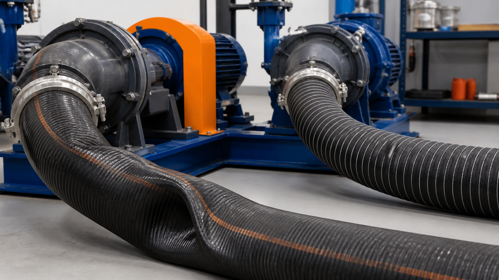
A spiral hydraulic hose is often considered for main boom, lift, telescope, winch, or other severe high-pressure circuits. Multi-spiral reinforcement can provide strong pressure and impulse performance, but it also affects outside diameter, weight, and minimum bend radius. Wire-braided constructions may provide better flexibility where their pressure and impulse ratings are adequate.
The correct choice balances hydraulic strength with the physical route. An oversized, overly stiff hose can transfer load into fittings or prevent a hose carrier from moving freely.
Outrigger Hose Requirements
Outriggers create a stable base by extending beams and applying vertical force through jacks. Their hoses may run through telescoping structures, around pivots, or underneath the carrier where road debris and contamination are common.
Check the route in fully retracted, partially deployed, and fully extended positions. The hose must not become taut, pinch between sliding members, form a loop that catches on a beam, or rub continuously against an edge. Guides and rollers should remain smooth and correctly aligned.
Because holding valves may trap pressure, service personnel must follow the crane manufacturer’s depressurization procedure. A hose that appears inactive may still contain stored energy. Outrigger assemblies also deserve close inspection because their failure can remove a stabilizing function.
Telescoping Boom Routing
Telescoping booms can use hose reels, energy chains, guide systems, or internally routed assemblies. These routes subject hoses to repeated bending and long travel. The hose must work within its minimum bend radius throughout the complete extension cycle.
Verify:
- The hose does not twist as sections extend.
- Reels and rollers match the hose diameter and bend requirement.
- Clamps control movement without crushing the cover.
- Couplings do not strike surrounding structures.
- The hose retains controlled slack without forming a snagging loop.
- Wear surfaces remain smooth and free of debris.
The layline provides a useful twist indicator. A layline that spirals around a hose intended to bend in one plane suggests incorrect installation or movement.
Abrasion, Impact, and Weather
Mobile cranes work on construction sites, roads, industrial plants, ports, and outdoor storage yards. Hoses may encounter dust, gravel, concrete residue, oil, rain, UV, ozone, and temperature extremes. Undercarriage and outrigger hoses can be hit by road debris, while boom assemblies rub if guides or clamps wear.
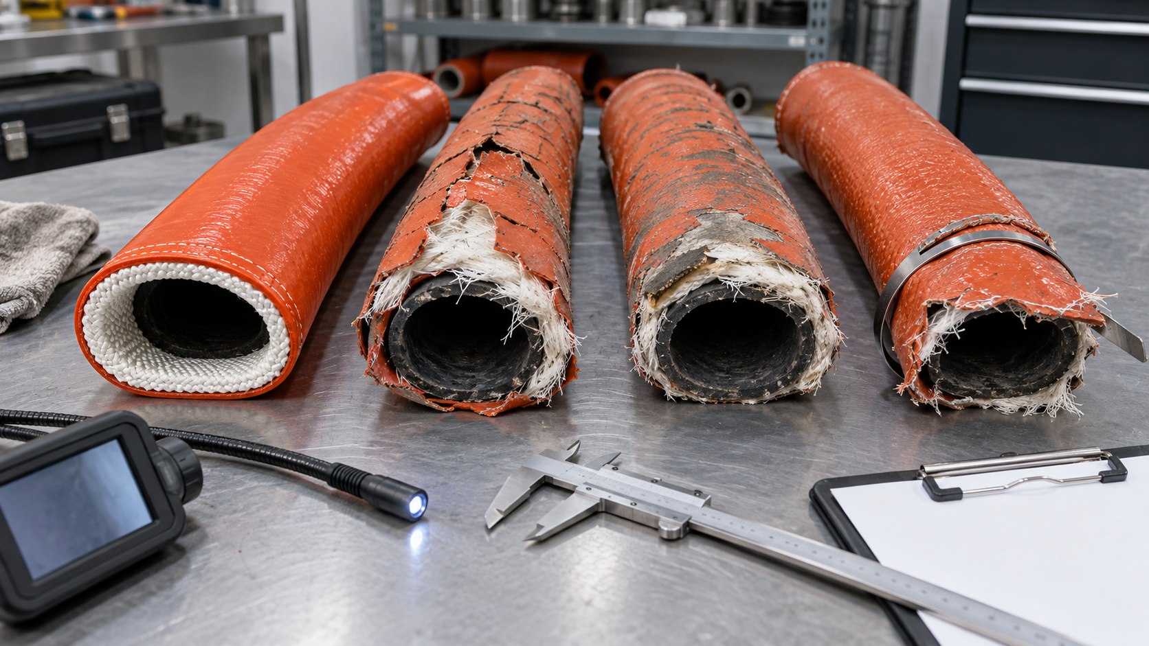
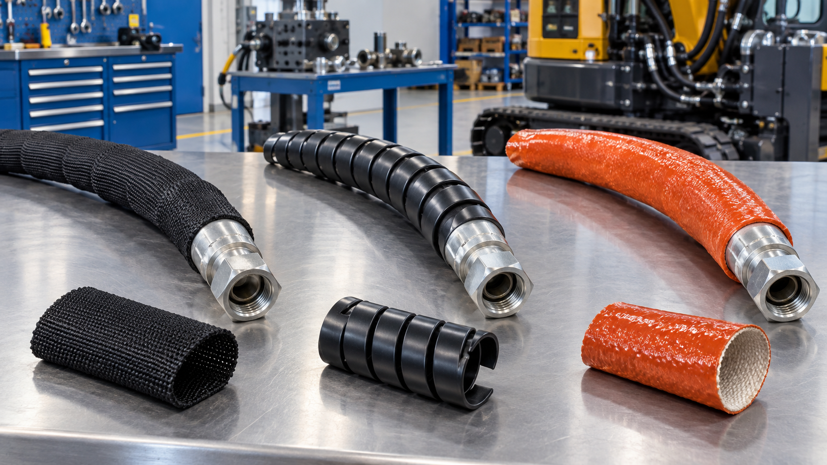
Choose an abrasion-resistant cover when justified, but correct the contact point first. Spiral guards, textile sleeves, and other protection can provide a sacrificial layer. Protection should not trap contamination, force a tighter bend, or conceal damage that needs inspection.
Near engines, exhaust after-treatment, or hot winch components, confirm ambient-temperature limits. A heat sleeve adds protection but cannot compensate for an underlying hose used beyond its approved fluid temperature.
Fluid and Temperature Compatibility
The tube must be compatible with the exact hydraulic fluid and its additives. Some cranes use biodegradable or fire-resistant fluids for particular projects. Provide the fluid manufacturer and full product name instead of a generic description.
Measure or estimate the minimum startup temperature, maximum fluid temperature, and local ambient temperature. Cold oil increases pressure loss and can raise return-line backpressure. Heat accelerates tube and cover aging and may reduce pressure capability.
Any fluid conversion should include hoses, seals, O-rings, accumulators, filters, flushing materials, and residual old oil. A compatible hose alone does not make the entire system suitable.
Fittings and Assembly Design
Use approved hydraulic hose end fittings with the specified ferrule and crimp dimensions. Mixing unvalidated hose and fitting components can cause tube damage, leakage, or fitting pull-off.
Confirm thread or flange standard, connection size, sealing method, material, pressure class, and angular orientation. Mobile fleets often contain mixed equipment, so visually similar metric, BSP, JIC, ORFS, and other connections must not be confused.
Minimize unnecessary adapters. A badly oriented elbow can create side load, while excess joints add leak points. For assemblies with two angled ends, record their rotational relationship accurately.
Custom hydraulic hose assemblies can incorporate controlled length, fitting orientation, guards, cleanliness, testing, and identification for a particular crane position. Customization should be supported by drawings, tolerances, approved materials, and change control.
Cleanliness and Installation
Contamination introduced through a replacement hose can damage valves, pumps, and load-holding components. Specify internal cleaning, end capping, and clean packaging. Keep caps installed until the assembly is connected.
During installation, do not force a hose into position by twisting it. Tighten connections using the correct procedure and support the fitting so torque is not transmitted into the hose. After installation, conduct the manufacturer’s functional and leak checks from a safe position.
Inspection and Replacement Planning
Inspect high-movement and high-consequence locations frequently, including boom pivots, telescope systems, outrigger beams, winches, and areas near clamps. Look for:
- Deep abrasion, cuts, or exposed reinforcement
- Kinks, flattening, crushing, or tight bends
- Cracks, blisters, hardening, or cover separation
- Leaks or movement at fittings
- Corrosion at ferrules, adapters, and clamps
- Twisted laylines or displaced guards
- Contact throughout full boom and outrigger movement
Never use a hand to locate a pressurized pinhole leak. Isolate stored energy and secure the crane before touching an assembly.
Record installation date, machine position, hours, inspection results, and removal reason. Repeated failure at one location should trigger a review of routing, length, support, pressure spikes, and protection.
RFQ Checklist
Provide the crane model, circuit and hose position, bore, cut length, continuous and peak pressure, impulse duty, fluid, temperature range, minimum bend radius, movement, external exposure, connection standards, fitting orientation, protection, cleanliness, testing, marking, certification, quantity, and packaging.
Drawings and a position-based hose database make replacements more consistent than copying a worn emergency assembly.
Final Selection Principles
Mobile crane hoses must combine pressure capacity with impulse endurance, controlled flexibility, abrasion resistance, compatible fittings, and safe routing. Outrigger and boom systems also require careful consideration of stored pressure and movement through their entire operating range.
When the hose specification is tied to the exact crane position and supported by disciplined inspection, fleets can reduce unexpected downtime and improve the reliability of lifting and stabilizing functions.